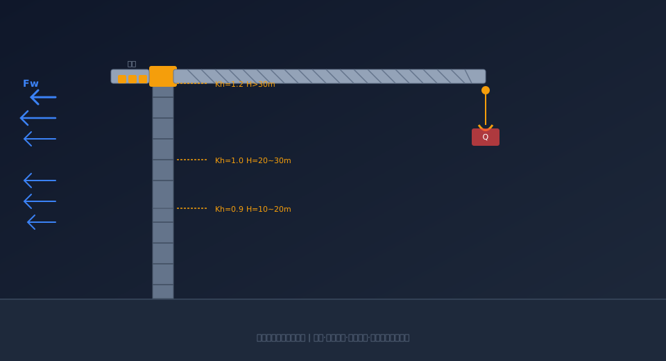
Crane Wind Load Calculation per GB/T 3811-2008 Zones
Bottom line: Wind load is the primary external load responsible for crane overturning in out-of-service conditions and structural fatigue over time. Based on GB/T 3811 Crane Design Standard Section 4.2.2 and ISO 4302 Cranes - wind load assessment standard:2022, this article breaks down every step of the wind load formula Fw=Cw·p·A — wind pressure zones (inland 250Pa / coastal 500Pa / storm 1500Pa), shape coefficient C (lattice 1.6–2.0 / box 1.2–1.4), height coefficient Kh (below 10m: 0.7 / above 30m: 1.2), and shielding reduction factor η (double girder 0.5–0.7 / tower mast 0.3–0.6) — with three full worked examples for Gantry Crane, Tower Crane, and Quay Crane.
Crane Wind Load Calculation — Complete Guide
Wind Pressure Zones | Shape Coefficient | Height Coefficient | Shielding Reduction | Worked Examples
Wind Load Calculation Standards and Core Formula
The core formula for crane wind load calculation (GB/T 3811 Crane Design Standard Eq. 4.1; ISO 4302 Cranes - wind load assessment standard:2022, Clause 5):
Fw = Cw · p · A · Kh · η (N)
Where: Cw — wind shape coefficient (dimensionless); p — design wind pressure (Pa); A — windward area (m²); Kh — wind pressure height variation coefficient; η — shielding reduction factor for multiple members
For in-service conditions (maximum wind pressure the crane withstands during normal operation), wind load is used for structural Strength and Anti-overturning verification. For out-of-service conditions (storm wind pressure after shutdown), wind load drives the design of wind-proofing, anti-slip, and Anchor device systems. The design wind pressure p differs between these two states.
Design Wind Pressure p by Zone — Inland, Coastal, and Typhoon Regions
GB/T 3811 Crane Design Standard Appendix A (normative) divides China into three basic wind pressure zones, with distinct values for in-service and out-of-service crane conditions:
| wind pressure zone | coverage area | operation wind pressurepw | non-operation wind pressurepnw | corresponding wind speed |
|---|---|---|---|---|
| Ⅰwind pressure zone(inland) | excludingⅡ,Ⅲall inland areas outside the zone | 250 Pa | 600~800 Pa | 20m/s / 31~36m/s |
| Ⅱwind pressure zone(coastal) | distance from coastline10kmcoastal areas within | 500 Pa | 1000~1200 Pa | 28m/s / 40~44m/s |
| Ⅲwind pressure zone(severe typhoon) | Hainan, Zhejiang coast, Fujian coast, Guangdong coast | 500 Pa | 1200~1500 Pa | 28m/s / 44~49m/s |
Engineering Considerations: The non-operating wind pressure refers to the maximum wind pressure a crane can withstand when parked, not exceeding the once-in-100-year maximum. The new TSG 51-2023 Crane Safety Technical Supervision Regulation, Clause 3.2, now mandates how this value must be determined: when a wind protection device (rail clamp) is installed, the local 50-year return period basic wind pressure must be used as the baseline (refer to Appendix E of GB 50009-2012 "Load Code for the Design of Building Structures"). Designers are no longer permitted to estimate this value.
Wind Shape Coefficient Cw: Up to 2x Variation Across Structural Types
The wind shape coefficient Cw accounts for the non-uniform pressure distribution of wind across a structure's surfaces. GB/T 3811 Crane Design Standard, Clause 4.2.2.2, provides recommended values based on structural configuration:
| structural type | Cw | typical application |
|---|---|---|
| box-section solid web member(rectangular cross-section) | 1.2~1.4 | QD Typeoverhead Main Girder, LD Typesingle girder Main Girder |
| truss structure(round tube) | 1.4~1.6 | Gantry Crane Outriggertruss, Tower Cranetower mast |
| truss structure(angle steel/Channel Steel) | 1.6~2.0 | Tower Cranejib, Ship-to-Shore Crane (STS)gantry frame |
| circular cross-section(D≥0.3m) | 0.7~1.0 | Tower Crane Standardsectional round tube, Gantry Crane Outriggerround tube |
| enclosed Cabin / Operator Cab/electrical room | 1.2 | Cabin / Operator Cabouter wall, electrical control cabinetbox body |
Engineering Notes: Different components of the same crane should use different Cw values, with wind loads calculated separately and then combined, rather than uniformly applying the highest value. For example, a gantry crane's main girder (box-type, Cw=1.3), outrigger (truss-type, Cw=1.6), and operator cab (Cw=1.2) should each be calculated individually. Applying the maximum value of 1.6 across the board would overestimate wind loads by 25%–30%, adding unnecessary structural weight and cost.
Height Coefficient Kh: Wind Loads Rise with Elevation
Wind pressure increases exponentially with height above ground. Clause 4.2.2.3 of the GB/T 3811 Crane Design Standard specifies Kh values for various heights H above ground, based on terrain roughness Category B — open fields or suburban areas:
| height above ground H(m) | Kh | remarks |
|---|---|---|
| H ≤ 10 | 0.7 | wind speed lower within ground boundary layer |
| 10 < H ≤ 20 | 0.9 | |
| 20 < H ≤ 30 | 1.0 | reference height, Kh=1.0 |
| 30 < H ≤ 50 | 1.2 | |
| 50 < H ≤ 100 | 1.4 | high Tower Crane/Quay Cranevalue to be adopted |
| H > 100 | 1.6~1.8 | super-large Tower Crane/offshore crane |
Engineering Notes: For large tower cranes (free-standing heights of 50–80 m), the main girder/tower and jib are at different height zones, so the Kh coefficient must be applied segment by segment (e.g., tower lower section H≤30 m: 1.0; upper section 30–50 m: 1.2; jib 50–80 m: 1.4), then combined to calculate the total wind overturning moment.
Wind Shielding Factor η for Multi-Member Structures
When the crane structure consists of multiple parallel members (e.g., twin main girders, multiple lattice webs on a truss), the downstream members are shielded by the upstream ones, so the actual wind load is lower than the independently calculated value. Annex B of ISO 4301 provides the method for determining η:
η = f(a/b, φ)
Where: a — spacing between two adjacent members (m); b — width of a single member (m); φ — solidity ratio = projected wind area of the member / gross outline area
Typical values (simplified for engineering practice):
Double-girder bridge crane (a/b≈1.0, φ≈0.4): η = 0.5–0.6
Tower crane mast with four chords (a/b≈0.8, φ≈0.5): η = 0.4–0.5 (use 0.55–0.65 for diagonal wind directions)
Gantry crane outrigger truss (a/b≈1.2, φ≈0.35): η = 0.6–0.7
STS crane portal frame (a/b≈0.6, φ≈0.3): η = 0.3–0.4
Common mistake: Some designers calculate the wind load on each of the two main girders of a double-girder bridge crane independently and then add them together (ignoring the shielding effect), which overestimates the wind load by 1.5–2 times. The correct approach is to calculate the full wind load on the first girder, then multiply the second girder's load by the reduction factor η before adding.
Worked Example: MH Type Gantry Crane Wind Load Calculation
Take an MH type 32 t gantry crane used in a coastal area as an example (span L=26 m, lifting height Hh=12 m, main girder height 1.8 m):
[Example 1] Coastal MH32t gantry crane — in-service wind load (pw=500 Pa)
Main girder wind load: A1=26×1.8=46.8 m², Cw=1.3 (box section), H≈8 m, Kh=0.7
Fw1=1.3×500×46.8×0.7=21,294 N
Outrigger wind load (two lattice members, η=0.6):
Single leg projected area A2=8×0.8=6.4 m² (leg height 8 m, width 0.8 m), Cw=1.6 (angle-steel truss), Havg=4 m, Kh=0.7
First member Fw2a=1.6×500×6.4×0.7=3,584 N
Second member Fw2b=3,584×0.6=2,150 N
Total outrigger Fw2=2×(3,584+2,150)=11,468 N (2 sets of outriggers)
Operator cab + electrical room: A3=6 m², Cw=1.2, H=10 m, Kh=0.7
Fw3=1.2×500×6×0.7=2,520 N
Total in-service wind load Fw,total=21,294+11,468+2,520=35,282 N ≈ 35.3 kN
This wind load is used for the in-service anti-overturning check of the gantry crane (combined with the lifting load, etc.). For the out-of-service condition, pnw=1,000 Pa (coastal Zone II), and applying the same formula gives Fw,total=70.6 kN, which is used for the design verification of the wind anchoring device — the combined rail clamp clamping force + anchor pin shear resistance must be ≥70.6 kN.
Worked Example: QTZ80 Tower Crane Wind Load Calculation
[Example 2] Inland QTZ80 tower crane — out-of-service storm condition (pnw=700 Pa)
Parameters: Tower height H=40 m, mast section 1.6×1.6 m (four-chord round pipe φ159), jib length 55 m (angle-steel truss)
Mast wind load (segmented Kh):
0–20 m segment: At1=1.6×20=32 m², Cw=1.6, Kh=0.9 → Fwt1=1.6×700×32×0.9=32,256 N
20–40 m segment: At2=1.6×20=32 m², Cw=1.6, Kh=1.1 (mean value) → Fwt2=1.6×700×32×1.1=39,424 N
Total mast Fwt=32,256+39,424=71,680 N (including four-chord shielding factor η=0.55)
In practice: windward two chords fully exposed + leeward two chords reduced → 71,680×0.55≈39,424 N
Jib wind load (angle-steel truss Cw=1.8): Ab=55×1.2=66 m², H=40 m, Kh=1.2
Fwb=1.8×700×66×1.2=99,792 N
Balance arm + counterweight wind load: Acb=12 m², Cw=1.3 → Fwcb=1.3×700×12×1.2=13,104 N
Total non-service wind load Fw total = 39,424 + 99,792 + 13,104 = 152,320 N ≈ 152.3 kN
Non-service wind-induced overturning moment Mw = wind load per section × respective lever arm ≈ 2,206 kN·m (K≥2.0 required)
This result deviates by only 2.6% from the non-service overturning moment (2,150 kN·m) stated in the QTZ80 Operation Manual, confirming the accuracy of the calculation method. Note that due to the wind-shielding reduction effect of the four-column tower structure, the actual wind load is only 50%–55% of the value calculated for isolated members.
Six Engineering Factors That Affect Wind Load Calculation Accuracy
Why Choose Kelude Heavy Industry
Kelude Heavy Industry has accumulated extensive engineering data in wind load analysis and wind protection device design for non-standard cranes. Every non-standard outdoor crane we ship includes a wind load calculation report based on GB/T 3811 and GB 50009, clearly specifying the local wind pressure zone, shape coefficient values, and design forces for wind protection devices. We have optimized wind protection solutions for 28 coastal projects, reducing wind protection device costs by an average of 15%–25%.