

Gantry Crane Span and Cantilever Matching: L/S Ratio and Wheel Load
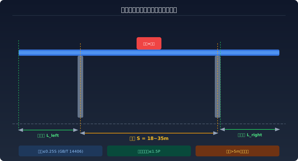
The ratio of span S to effective cantilever overhang L is the core parameter governing overall stability and wheel load distribution in gantry cranes.Per ISO 4306 (General-Purpose Gantry Crane), the effective cantilever overhang should generally not exceed 0.25 times the span S, and the maximum wheel load at the cantilever end must not exceed 1.5 times the wheel load at the outrigger. When the overhang exceeds 5 m, a full anti-overturning stability check is mandatory, with a safety factor of no less than 1.33.
Gantry cranes are widely used in open storage yards, rail freight terminals, precast concrete plants, and shipyard workshops. The structure consists of a main girder, two outriggers, a crane travel mechanism, and a hoisting trolley. Span S and overhang L are the two primary geometric parameters in gantry crane design, as they directly determine the crane's coverage area, wheel load distribution, crane rail foundation loads, and anti-overturning safety margin. The design must strike an optimal balance between maximizing coverage and ensuring structural safety and cost efficiency.
From an engineering standpoint, many older gantry crane designs blindly extended the cantilever to increase the working envelope, leading to excessive wheel loads at the cantilever end, increased outrigger deflection, and uneven settlement of the rail foundation. A proper understanding of the constraint relationship between span and overhang is therefore the first step in gantry crane selection and design. The following analysis covers design principles, selection specifications, and common pitfalls.
Design Principles of Span and Overhang
The span S of a gantry crane is the horizontal distance between the centerlines of the crane rails beneath the two outriggers, and it defines the load-carrying distance of the main girder between the outriggers. The overhang L refers to the portion of the main girder extending beyond the outriggers, and it comes in two configurations: single cantilever (overhang on one side only) and double cantilever (overhang on both sides). In box-type main girder gantry cranes, the maximum bending moment occurs at mid-span or at the cantilever root, and its magnitude is proportional to S² and L².
The main girder section height H is typically taken as S/14 to S/18. For every 1 m increase in overhang length, the bending moment at the cantilever root increases by approximately 8%–12% (based on a 20 t / 30 m span machine), while wheel load increases by about 5%–8%. When the L/S ratio rises from 0.15 to 0.30, the maximum wheel load can increase by roughly 25%–35%, placing significantly higher demands on the rail foundation's load-bearing capacity. ISO 4306 explicitly specifies that the effective cantilever overhang L should generally be S/4 to S/6, with an absolute maximum of S/3.5.
The structural diagram below illustrates the key geometric parameters of a gantry crane — the relationship between span S, left overhang L_left, and right overhang L_right:
Key Constraints in Crane Selection and Design
1. Wheel Load Limits — This is the primary constraint on cantilever length. Each outrigger of a gantry crane typically has 2 or 4 wheels, and the maximum wheel load P_max is determined jointly by the crane rail section and the foundation bearing capacity. Taking the commonly used P43 rail as an example, the allowable wheel load is approximately 250–300 kN. When lifting the rated load at the cantilever end with an overhang L = 5 m (20 t / 30 m machine), the wheel load on that outrigger can reach 320 kN, which exceeds the allowable range for P43 rail — requiring either a heavier QU70 rail or an increased number of wheels.
2. Anti-Overturning Stability — When a gantry crane lifts a full load at the cantilever end, the entire machine is at risk of overturning about the outrigger. Per ISO 4306, under the most unfavorable load combination (lifting 1.25 times the rated load at the cantilever end plus wind load), the anti-overturning safety factor must not be less than 1.33. When the overhang L exceeds 5 m, a stability check is recommended even when lifting only the rated load; if necessary, counterweights should be added at the outriggers or the track gauge widened.
3. Main Girder Deflection Control — When lifting at the cantilever end, the cantilever deflection f_L is controlled to f_L ≤ L/350. For L = 6 m, the allowable deflection is approximately 17 mm. Excessive cantilever deflection not only compromises positioning accuracy but also increases trolley climbing resistance and adds load to the travel motor.
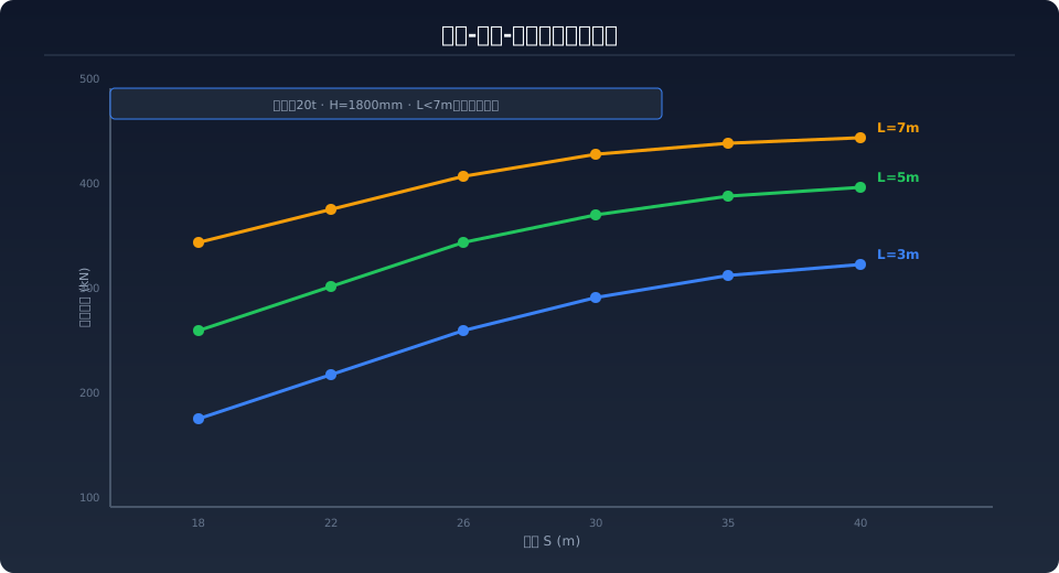
The chart below shows how the maximum wheel load varies with span S at different overhang lengths L — note that the larger the overhang, the more sensitive the wheel load becomes to changes in span:
Engineering Parameter Comparison Across Span and Overhang Combinations
Key takeaway: An L/S ratio in the range of 0.12–0.25 delivers the best combination of code compliance and cost efficiency; beyond 0.25, wheel load and anti-overturning safety factor deteriorate rapidly.The comparison table below lists the key design parameters for a 20 t gantry crane across three typical spans (22 m / 26 m / 30 m) and three typical overhangs (3 m / 5 m / 7 m). Data is based on a Q235B (≈S235JR) box-type main girder section, with a Work Duty of A5, and is intended as a reference for crane selection.
| Span S (m) | overhang L (m) | L/S ratio | Main Girdercross-section H (mm) | Maximum Wheel Load (k N) | Recommended rail | overturning Safety factor |
|---|---|---|---|---|---|---|
| 22 | 3 | 0.14 | 1400 | 218 | P43 | 2.15 OK |
| 22 | 5 | 0.23 | 1400 | 268 | P43/P50 | 1.72 OK |
| 22 | 7 | 0.32 | 1600 | 342 | QU70 WARN | 1.35 WARN |
| 26 | 3 | 0.12 | 1600 | 235 | P43 | 2.38 OK |
| 26 | 5 | 0.19 | 1600 | 285 | P50 | 1.85 OK |
| 26 | 7 | 0.27 | 1800 | 358 | QU70 FAIL | 1.28 FAIL |
| 30 | 3 | 0.10 | 1800 | 252 | P50 | 2.62 OK |
| 30 | 5 | 0.17 | 1800 | 305 | P50/QU70 | 1.95 OK |
| 30 | 7 | 0.23 | 2000 | 372 | QU80 FAIL | 1.42 WARN |
Note: OK indicates compliance with GB/T 14406-2011 with a safety margin; WARN indicates a critical state requiring detailed verification; FAIL indicates non-compliance requiring design parameter adjustments.
The table above shows that when the L/S ratio falls within the 0.12–0.25 range, all indicators meet the specification requirements while maintaining good cost efficiency. Once L/S exceeds 0.25, wheel load and anti-overturning safety factors deteriorate rapidly, necessitating a significant increase in main girder section height or an upgrade in crane rail model—both of which drive up project costs considerably. Taking the S=26m/L=7m configuration as an example, the anti-overturning safety factor is only 1.28, below the required 1.33, meaning additional counterweight or a wider rail gauge would be mandatory to achieve compliance.
Safety Design Reminder
Per GB/T 28264-2017 Safety Monitoring and Management System for Lifting Appliances, gantry cranes with an overhang exceeding 5m or an L/S ratio greater than 0.2 must be equipped with a crane travel skew monitoring device and a real-time wheel load monitoring system. When the skew between the two outrigger sides exceeds S/800, the system should trigger an alarm and initiate automatic correction. Additionally, when lifting a rated load at the cantilever end, the long-travel mechanism must remain stationary until the load is confirmed stable, after which lateral movement may proceed.
Common Selection Mistakes and Optimization Tips
Mistake 1: Assuming a longer cantilever always means better coverage. Extending the cantilever from 5m to 7m increases the coverage area by roughly 40%, but it also pushes the maximum wheel load up by over 30%, requires upgrading the crane rail from P50 to QU80, and adds approximately 60% to civil construction costs. For most bulk cargo yards, a 5m cantilever already covers two rail lines or three rows of storage; the marginal benefit of a 7m cantilever is rarely justified.
Mistake 2: Focusing only on strength while overlooking deflection. Some designers check normal and shear stresses but fail to account for how cantilever-end deflection affects operational performance. When deflection at the cantilever tip exceeds L/350, the trolley must overcome an additional grade (roughly 1:175) when traveling toward the cantilever end, requiring at least a 15% increase in motor power reserve.
Mistake 3: Ignoring the impact of uneven foundation settlement. Differential settlement of the crane rail foundations on either side can cause outrigger skew, which in turn amplifies the actual wheel load at the cantilever end. Long-term monitoring data indicates that rail foundations in soft-soil areas can settle 5–15mm per year. For designs with a cantilever L>5m, it is recommended to incorporate adjustable rail seats with a height adjustment range of ±20mm.
Optimization Tip: For existing gantry cranes where a longer cantilever is required by operational needs, the preferred approach is to first increase the rail gauge B (distance between outrigger centers) to enhance anti-overturning capability. Every 500mm increase in rail gauge B improves the anti-overturning safety factor by approximately 8%–12%. Additionally, adding concrete counterweights (about 3–5t) at the outrigger on the cantilever side can further improve wheel load distribution.
Frequently Asked Questions
Q: What is the recommended ratio range between the span S and the cantilever L for a gantry crane?
A: According to GB/T 14406-2011 and engineering practice, the single-side cantilever L of a double-cantilever gantry crane is typically set at S/6 to S/4 (i.e., L/S = 0.12–0.25), with an absolute maximum of S/3.5. When L/S falls within the 0.15–0.25 range, wheel load, deflection, and anti-overturning stability can generally be satisfied simultaneously, while keeping rail and foundation costs within a reasonable range.
Q: How can excessive wheel load at the cantilever end be resolved? Are there alternatives to upgrading to a heavier rail?
A: Four technical solutions are available for excessive wheel load: increasing the number of wheels on the outrigger (from 2 to 4 wheels) reduces wheel load by about 40%–45%, though this requires modifying the equalizing beam structure; adding concrete counterweights (3–5t) at the cantilever-side outrigger reduces wheel load by roughly 10%–15%; reducing the cantilever length (e.g., from 7m to 5m) cuts wheel load by approximately 25%–30%; and widening the rail gauge B, where each 500mm increase reduces cantilever-side wheel load by about 6%–9%. The most suitable approach depends on site constraints and budget.
Q: What items need to be verified when extending the cantilever of an existing gantry crane?
A: Extending the cantilever is a major retrofit that requires four mandatory checks: strength verification of the main girder section at the cantilever root (normal stress not exceeding the allowable value divided by 1.33, with the same factor applied to shear stress); deflection verification at the cantilever tip (not exceeding L/350), requiring an increase in main girder height or the addition of truss stiffening if not met; overall machine anti-overturning stability verification (safety factor not less than 1.33); and wheel load verification (not exceeding the rail's allowable limit), requiring additional wheels or a rail upgrade if not met. The retrofit plan must be submitted to the local special equipment inspection body for approval.
Q: What are the differences in span design between single-cantilever and double-cantilever gantry cranes?
A: A single-cantilever gantry crane has an overhang on only one side of the main girder, so its span S is typically 2–4m smaller than that of a double-cantilever model of the same capacity (since the concentrated effect of a single-side overhang on overturning is more pronounced). Additionally, the wheel load difference between the cantilever side and the non-cantilever side must be calculated separately, as it typically reaches 30%–50%, requiring distinct considerations in rail foundation design. In contrast, a double-cantilever gantry crane with symmetrical overhangs exhibits a smaller wheel load difference (about 10%–20%), allowing for a more balanced foundation design. The final selection should be based on site conditions and operational workflows.
