

Double-Girder Bridge Crane Rail Gnawing: Causes & Fixes
Wheel rail gnawing in double-girder bridge cranes occurs when the wheel flanges make abnormal contact with the side of the crane rail, causing rapid wear on both the flange and the rail head. Common causes fall into six categories, including excessive rail installation deviation, out-of-tolerance wheel block alignment, and diagonal deformation of the crane frame. In mild cases, wheel service life drops by 50%–70%; in severe cases, derailment can occur.
Wheel rail gnawing is one of the most common mechanical faults in double-girder bridge crane operation. Per ISO 12478 (replacing GB/T 10183-2018), the normal clearance between the wheel flange and the rail side is 5–10 mm. Once this clearance is compromised, the flange begins to cut into the rail head. In a 2024 inspection at a steel mill's hot rolling workshop, three of four QD-type 32 t double-girder bridge cranes showed varying degrees of flange rubbing. The worst case had 7 mm of flange wear (original thickness: 15 mm), with the rail head side gouged into a deep groove—replacement costs exceeded CNY 80,000 (approx. $11,800) per occurrence. This article systematically covers the root causes, diagnostic procedures, and corrective measures for wheel rail gnawing.
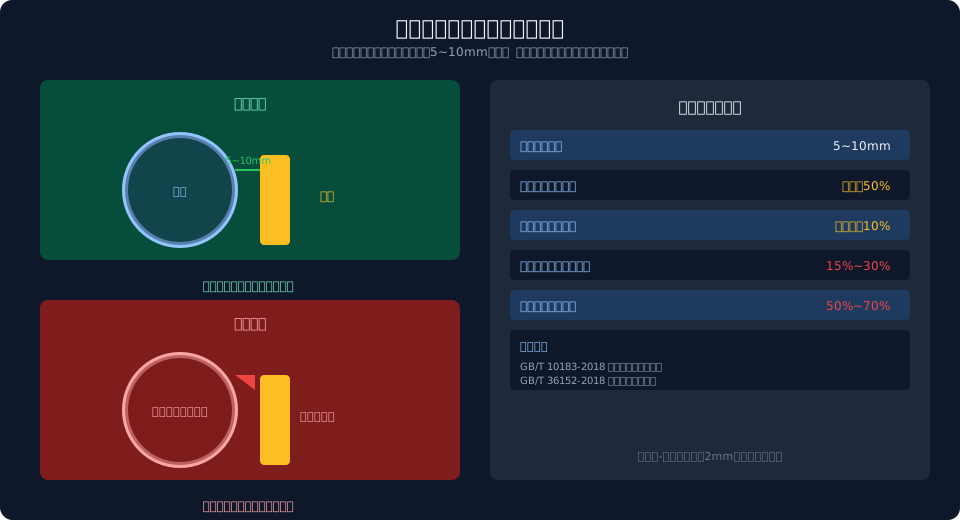
Typical Signs and Consequences of Wheel Rail Gnawing
The most immediate symptom of flange rubbing is increased travel resistance—bridge drive motor current runs 15%–30% above normal, and in severe cases can trip the overcurrent protection. The inner face of the wheel flange develops a bright metallic sheen or blue discoloration (from friction heat), while the rail head side becomes cut with stepped grooves.
The knock-on effects of wheel rail gnawing form a long chain: flange wear reduces wheel diameter → the two sides of the crane run at different linear speeds → gnawing worsens, creating a vicious cycle. Per ISO 4306 (replacing GB/T 36152-2018), a wheel flange worn beyond 50% of its original thickness must be scrapped. Continued gnawing also loosens or fractures rail clamp bolts and creates step offsets at rail joints. The most noticeable warning signs for the operator are abnormal noise (sharp metallic scraping) and periodic vibration during travel.
Six Root Causes of Wheel Rail Gnawing
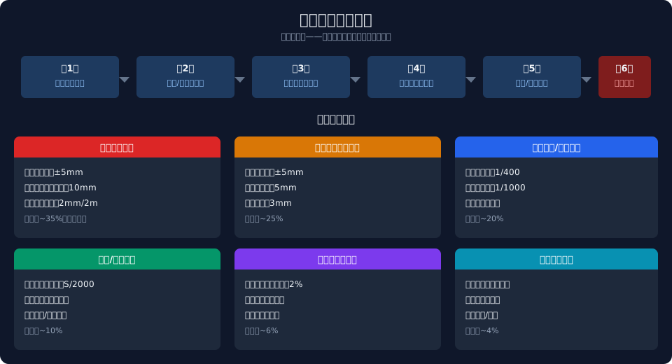
Field data analysis groups the causes of wheel rail gnawing in double-girder bridge cranes into six categories, listed here in descending order of frequency:
Excessive rail installation deviation—accounts for roughly 35% of gnawing faults, making it the leading cause. When track gauge deviation exceeds ±5 mm, the elevation difference between the two rail tops at the same cross-section exceeds 10 mm, or lateral straightness exceeds 2 mm per 2 m, the wheel is forced into contact with the rail side on every travel cycle. Per ISO 12478 (replacing GB/T 10183-2018), installation tolerance control during rail laying determines operating quality for the next 5–8 years.
Out-of-tolerance wheel block coaxiality and alignment—accounts for about 25% of gnawing faults. Span deviation across the four wheels exceeding ±5 mm, diagonal difference over 5 mm, or same-end-carriage wheel alignment offset beyond 3 mm creates a yaw moment that forces the flanges to continuously press against the rail. Mismatched wheel tread diameters (side-to-side difference over 0.5 mm on the same crane) also produces linear speed differences.
Vertical and horizontal wheel inclination—accounts for roughly 20% of gnawing faults. When vertical inclination exceeds 1/400 (i.e., more than 1 mm on a 400 mm diameter wheel) or horizontal inclination exceeds 1/1000, the wheel no longer rolls purely on the rail but skids sideways, keeping the flange in constant frictional contact. New cranes typically ship with inclination held within 0.5/1000; after 2–3 years of service, bearing wear and loose angle bracket bolts can push it out of tolerance.
Bridge frame structural deformation—accounts for about 10% of gnawing faults. Main girder lateral bow exceeding 1/2000 of the span, or end carriage plastic deformation from impact or fatigue, transfers to the wheel blocks and destroys the original installation accuracy. Long-term overload and off-center loading (e.g., always lifting heavy loads on the same side) are the main drivers of frame deformation.
Unsynchronized dual-side drive—accounts for about 6% of gnawing faults. Double-girder bridge cranes use independent drives on each side. When the speed difference between the two motors exceeds 2%, brake release time difference exceeds 0.3 seconds, or drive shaft coupling clearance is excessive, the two sides travel at different speeds and the crane yaws continuously—gnawing is unavoidable.
Uneven foundation settlement of the crane rail—accounts for about 4% of gnawing faults. Uneven column settlement, long-term deflection of the runway beam, and loose or broken rail clamp bolts all ultimately show up as changes in rail geometry. This type of gnawing is especially common in factory buildings over five years old.
Six-Step Diagnostic Procedure for Wheel Rail Gnawing
Once gnawing signs are detected, work through the following six steps from simplest to most involved to avoid unnecessary dismantling:
Step 1: Visual inspection—With the crane parked and power off, use a strong flashlight to examine all wheel flanges and rail sides. Look for bright metallic sheen on the flange (normal is dull gray), blue discoloration (high-temperature oxidation), and stepped grooves on the rail head side. Photograph the wear locations (which side, which end) to make an initial judgment of the gnawing direction.
Step 2: Track gauge and levelness measurement—Using a track gauge or laser distance sensor, measure the track gauge every 2 m along the full rail length. Deviation should not exceed ±5 mm (per ISO 12478, replacing GB/T 10183-2018). Use a spirit level to check the elevation difference between the two rail tops at the same cross-section—it should not exceed 10 mm. Pay special attention to rail joints: step offsets and excessive gaps are common sources of localized gnawing.
Step 3: Wheel alignment check—Stretch a reference wire along the outside of the end carriage (about 50 mm from the wheel tread) and use an inside micrometer to measure the distance from each wheel tread to the wire. The reading difference between the two wheels on the same end carriage should not exceed 3 mm; span deviation across all four wheels should not exceed ±5 mm; diagonal difference should not exceed 5 mm.
Step 4: Frame diagonal verification—Using the four wheel axle centers as reference points, measure both diagonals with a steel tape or laser rangefinder. A difference exceeding 5 mm indicates frame twist or parallelogram deformation. Check whether the end carriage-to-main girder connection bolts are loose and whether the end carriage itself has plastic deformation.
Step 5: Wheel vertical/horizontal inclination measurement—Set up a theodolite or laser alignment instrument in front of the wheel to measure the vertical inclination of the wheel tread relative to the rail. Vertical inclination should not exceed 1/400; horizontal inclination should not exceed 1/1000 (per JB/T 6392-2017). If out of tolerance, check the angle-type bearing housing bolts and shims.
Step 6: No-load test run—After completing the static checks in steps 1–5, run the crane empty for a full round trip. Observe the wheel-to-rail contact and listen for uniform running sound. Periodic abnormal noise (e.g., a creak every 3–5 seconds) typically corresponds to one gnawing pulse per wheel revolution. Record motor current on both sides; a difference exceeding 10% is abnormal.
Safety Notice—Before performing rail or wheel inspections, disconnect the main power supply to the crane bridge and post a "Do Not Energize" warning tag. When walking on the rails to take measurements, confirm that cranes on adjacent bays are stopped or maintain a safe distance. Work at height (runway beam elevation is typically 6–15 m) requires a double-hook safety belt, and measuring tools must be secured with lanyards. Before dismantling wheel blocks, support the end carriage reliably with jacks—never work on a wheel block suspended only from the crane hook.
Corrective and Preventive Measures for Wheel Rail Gnawing
Depending on the diagnostic findings, corrective action falls into two tiers: adjustment/repair and replacement/overhaul.
Daily inspection—Before taking over the crane, walk a full circle around it and visually check the rail surface for fresh metal shavings (the most direct evidence of gnawing) and for abnormal brightness on wheel flanges. Record any findings in the shift handover log.
Monthly focused check—Use a feeler gauge to measure the clearance between the wheel flange and the rail side at both ends of each wheel (8 data points total). If any point reads less than 2 mm, initiate the diagnostic procedure. Check rail clamp bolt tightness and verify with a torque wrench to the design value (M20 bolts: 200–250 Nm).
Quarterly precision check—Measure track gauge and elevation difference across the full rail length using a track gauge and spirit level. Re-verify wheel alignment using the wire reference method. If measurements fall outside the allowable range per ISO 12478 (replacing GB/T 10183-2018), develop a correction plan. Check the tightening torque of angle-type bearing housing bolts—looseness is an early indicator of wheel inclination drift.
Annual overhaul—Dismantle and inspect wheel blocks: measure remaining flange thickness (replace if less than 50% of original), tread diameter (if side-to-side difference on the same crane exceeds 0.5 mm, replace both wheels), and bearing clearance (replace if radial clearance exceeds 0.2 mm). Realign the full rail system: re-lay the reference line, level with base plates, and retighten clamps.
For rail gnawing caused by track installation deviations, loosen the rail clamps, shim steel plates (0.5–3 mm thick) under the rail base, and use a spirit level to checkation deviations, loosen the rail clamps, shim steel plates (0.5–3 mm thick) under the rail base, and use a spirit level to check alignment section by section before re-tightening the clamps. Correct rail gauge deviations by shifting the entire rail laterally in increments no greater than 3 mm per pass, then run a full test cycle to confirm the wheel no longer rubs before final tightening.
When wheel block skew exceeds tolerance, loosen the anchor bolts on the angle-type bearing housings and insert or remove shims (0.1–0.5 mm per piece) between the housing and the end carriage to adjust both vertical and horizontal wheel alignment. After adjustment, re-measure the squareness and diagonal dimensions of all four wheels to ensure the three indicators are simultaneously within spec. A typical adjustment takes 4–6 hours.
For synchronization issues between the two drive sides, remediation options are tiered by upgrade complexity. The basic approach is to recalibrate the VFD parameters so both motors' rotational speed setpoints match (deviation within 0.5%). The intermediate solution adds encoder feedback for closed-loop synchronization control. The definitive fix—applicable to double-girder cranes with spans up to 22.5 m—is to replace the dual-motor arrangement with a single motor and extended drive shaft, eliminating the root cause of asynchronous operation entirely.
Rail Gnawing Troubleshooting Quick Reference
| Wheel rail gnawing / flange rubbing Phenomenon | Root Cause | Rapid Diagnostic Method | Priority Inspection Item |
|---|---|---|---|
| Continuous Throughout Wheel rail gnawing / flange rubbing, Both Sides of Rail Head Wear | Track Gauge / Rail Gauge Undersized | Track Gauge / Rail Gauge At Every Interval of...2mMeasure Track Gauge / Rail Gauge | Track Gauge / Rail Gauge Whether Less Than Design Value3mmand Above |
| Only At Crane Rail A Certain Section Wheel rail gnawing / flange rubbing | Crane Rail Local Bending/Joint Misalignment | Check This Section with a Stretched Wire Straightness | Rail Joint Gap and Misalignment Amount at the Location |
| Only One Side Worn Crane Rail(e.g., Only Left Rail Worn) | Wheel Alignment (Same Position)/Diagonal Tolerance Exceeded | Measure Four-Wheel Alignment with Stretched Wire | Whether Diagonal Difference Exceeds5mm |
| Wheel rail gnawing / flange rubbing Periodic Pulsation(Rhythmic Sound) | Out-of-Round Wheel/Tread surface Wear Uneven | dial micrometer Measure Tread surface Runout | Whether Radial Runout Exceeds0.5mm |
| Obvious Torsional Sway of the Crane During Operation | Two-Side Drive Not...Synchronization | clamp meter Measure Both Sides Simultaneously Current | Both Sides of Rail Head Current Whether Diagonal Difference Exceeds10% |
| New Crane3Occurring Within... Months Wheel rail gnawing / flange rubbing | Installation Quality or Factory...Accuracy Insufficient | Recheck Installation Against Factory Report Tolerance | Track Gauge / Rail Gauge, Wheel Alignment (Same Position), Deviation Amount |
Myth #1: Just replace worn wheels and you're done — If you don't fix the underlying rail installation deviation and wheel alignment issues, the new wheels will start flange rubbing again within a month. The right approach is to first identify and correct the root cause (rail alignment or wheel block adjustment), then replace wheels that have exceeded their wear limits.
Myth #2: Greasing the wheel flange will ease flange rubbing — Grease contaminates the tread surface, reduces the adhesion coefficient between wheel and rail, and leads to slip at startup and longer braking distances. Flange rubbing is a geometry problem, not a friction problem — lubricating it is not only ineffective, it creates a new safety hazard.
Myth #3: A wider track gauge is better than a narrower one — An oversized gauge causes the wheels to snake along the rail, with flanges alternately striking both rail heads. Only when the gauge sits squarely within the tolerance band (±5mm) can the wheels run stably. Both oversize and undersize are unacceptable.
Frequently Asked Questions
Q: What's the difference between flange rubbing on a double-girder bridge crane and on a single-girder crane?
A: On a double-girder bridge crane, flange rubbing typically occurs in the crane travel mechanism — specifically between the end carriage wheels and the factory building rails. Because the double-girder design has a large span (typically 10.5–31.5m) and high dead weight, insufficient end carriage stiffness can cause deformation that leads to flange rubbing. On a single-girder crane (LD Type), the long-travel mechanism consists of an electric hoist running along the lower flange of an I-beam. Here, flange rubbing shows up as the hoist wheel flange wearing against the I-beam's lower flange edge, usually caused by the I-Beam rail failing to meet straightness and levelness requirements. The troubleshooting process is similar for both, but the measurement reference points and adjustment methods differ.
Q: How severe does flange rubbing have to get before the crane must be shut down for immediate repair?
A: Per the scrapping criteria in JB/T 6392-2017, the crane must be taken out of service if any of the following conditions is met: ① Wheel flange wear exceeds 50% of the original thickness; ② Lateral wear on the rail head exceeds 10% of the rail head width; ③ Rail Clamp fracture or loose bolts exceed 20% of the total clamps in that section; ④ The wheel shows a tendency to jump the rail during operation (flange top approaching the rail head top). If routine inspection finds the gap between flange and rail has dropped below 2mm and is still deteriorating, schedule a planned shutdown for maintenance — don't wait until the flange wears through.
Q: Is there a way to monitor flange rubbing online without removing the wheels?
A: Three online monitoring approaches are available today: ① Mount a laser displacement sensor on the crane end carriage to measure the gap between the wheel flange and the rail in real time, with accuracy up to ±0.1mm; ② Install a vibration sensor on the wheel bearing housing — the characteristic frequency generated during flange rubbing (high-frequency harmonics at integer multiples of the wheel rotation frequency) serves as an early warning signal; ③ Apply reflective markers to the rail side and use an onboard vision camera to capture rail condition, then assess rail head wear through image recognition. These solutions have already been deployed in Kelude Heavy Industry's smart overhead crane retrofit projects, shortening flange rubbing detection from a monthly manual inspection cycle to real-time monitoring.
Q: What are the complete rail installation tolerance requirements in GB/T 10183-2018?
A: GB/T 10183-2018 specifies the installation tolerances for wheels and rails on bridge and gantry cranes. The core requirements are: track gauge deviation no more than ±5mm (±3mm for spans of 16m or less); elevation difference between the two rail tops at the same cross-section no more than 10mm (6mm for spans of 16m or less); lateral rail straightness no more than 2mm per 2m; rail joint gap no more than 2mm with vertical misalignment no more than 1mm; wheel span deviation no more than ±5mm, diagonal difference no more than 5mm, and alignment difference no more than 3mm. These tolerance values serve as the baseline for flange rubbing diagnosis — any reading outside these limits should be added to your corrective action plan.
