

Crane Automation Control Systems Explained
A crane automated control system is an integrated electrical and information system built on a PLC core, VFD-driven power delivery, and a sensor network for perception. It spans five automation levels—from manual operation to fully unmanned—delivering a complete closed control loop of sensing, decision-making, actuation, and feedback.
A crane automated control system integrates a programmable logic controller (PLC) as the central control brain, variable-frequency drives (VFDs) as the power actuation hub, a sensor system for perception, an industrial communication network for data transmission, a safety control system as the protective barrier, and a Human-Machine Interface (HMI) with a remote monitoring platform for operator interaction. The operating principle is as follows: sensors—including absolute encoders, laser distance sensors, and gray-code bus positioning systems (Gray-code bus positioning system)—continuously capture real-time status data such as position, speed, load, and sway angle. This data is transmitted via PROFINET/PROFIBUS industrial bus to the PLC controller (Siemens S7-1200 for standard control applications, S7-1500 for high-speed, high-precision tasks). The PLC executes user-programmed control logic—covering sequential control, PID closed-loop regulation, input-shaping anti-sway algorithms, and safety interlock routines—and outputs commands to the VFDs (Siemens SINAMICS G120/V90) to drive the motors. Simultaneously, the HMI (Siemens KTP series or Weinview) and the remote monitoring system provide human-machine interaction and data visualization, completing the full spectrum of crane operations from manual control to fully automated, unmanned intelligent handling.
With the advancement of Industry 4.0 and Smart Manufacturing, lifting appliances—as critical material handling equipment—are undergoing a profound transformation from traditional manual control toward digitalized, intelligent, and unmanned operations. Kelude Heavy Industry, with years of expertise in crane manufacturing and deep integration of the Siemens industrial automation ecosystem, has developed a complete crane automation control portfolio spanning five levels: manual operation, wireless remote control, semi-automatic, fully automatic, and fully unmanned. This article provides a comprehensive analysis covering control system architecture, PLC design, variable-frequency speed control, positioning and anti-sway technology, safety control, communication networks, remote monitoring, and MES/WMS system integration.
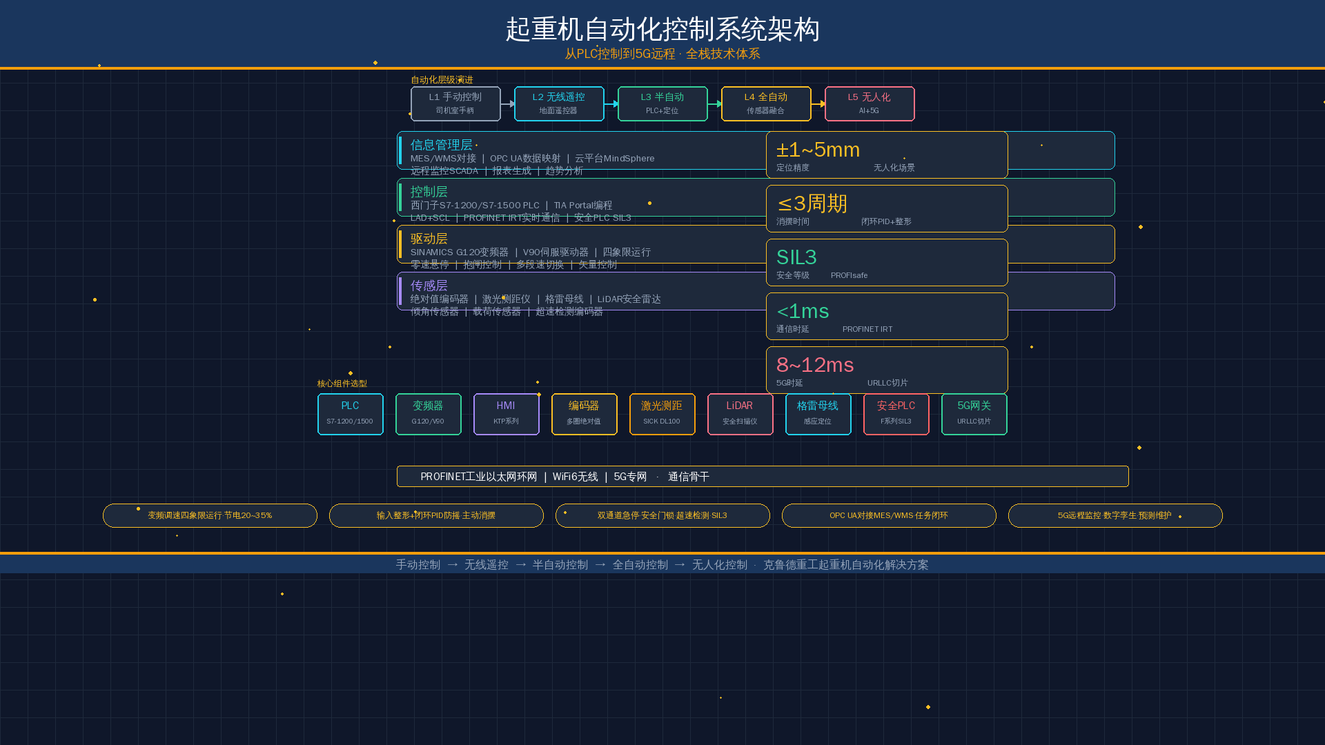
Control System Architecture Overview
The crane automated control system adopts a hierarchical architecture with four distinct layers, from bottom to top: the field device layer, the control layer, the monitoring layer, and the information management layer. The field device layer comprises sensors (absolute encoders, laser distance sensors, limit switches, load sensors, LiDAR, etc.) and actuating mechanisms (variable-frequency motors, brakes, hydraulic thrusters, etc.). The control layer, built around Siemens S7-1200 or S7-1500 series PLCs, executes real-time control programs and safety logic. The monitoring layer provides a local operator interface via HMIs (Siemens KTP700/1200 series or Weinview MT/iP series touch screens). The information management layer connects via industrial Ethernet to host servers, databases, and enterprise MES/WMS systems, enabling bidirectional exchange of production scheduling data.
For communication, the control system backbone network employs a PROFINET industrial Ethernet ring topology with isochronous real-time (IRT) mode, ensuring data exchange latency of less than 1 millisecond between slave devices. The wireless communication layer uses a WiFi 6 (IEEE 802.11ax) access point paired with industrial-grade wireless clients, meeting the real-time data transmission requirements of moving components such as trolleys and slewing mechanisms. For remote monitoring scenarios, a 5G SA (standalone) architecture is deployed, keeping end-to-end latency within 10 ms and supporting simultaneous transmission of HD video streams and real-time control data.
Kelude Heavy Industry's crane automation control framework is categorized into five development stages based on the degree of automation. The comparison table below highlights the core differences across these levels:
| Level | Control Mode | Key Features | Typical Applications |
|---|---|---|---|
| Level 1 | Manual operation | Pendant control or cab operation; operator relies on visual judgment; basic motor starting and stopping; no automated positioning. | Small workshops, low-duty-cycle applications, occasional lifting tasks. |
| Level 2 | Wireless remote control | Handheld or pendant wireless remote; variable-frequency speed control for smooth start/stop; basic overload and limit protection; improved operator safety and mobility. | General manufacturing, warehouses, assembly lines. |
| Level 3 | Semi-automatic | PLC-based automated sequences for predefined moves (e.g., trolley positioning, hoist height control); encoder and limit switch feedback; HMI for parameter setting and diagnostics; single-axis or multi-axis coordinated motion. | Production lines with repetitive handling cycles, process-critical lifting. |
| Level 4 | Fully automatic | Full PLC automation with absolute encoders and laser positioning; automatic anti-sway control; automatic target recognition and path planning; integration with WMS/ERP for task scheduling; remote monitoring and diagnostics. | Automated warehouses, container yards, steel coil handling, high-throughput production. |
| Level 5 | Unmanned / Autonomous | Fully autonomous operation with no on-site operator; AI-based path optimization and collision avoidance; 5G/Wi Fi 6 communication for real-time fleet management; predictive maintenance and digital twin integration; 24/7 continuous operation. | Smart factories, fully automated logistics hubs, dark warehouses, unmanned ports. |
| Control Mode | Operation Mode | Positioning Accuracy | Application Scenarios | Investment Grade |
|---|---|---|---|---|
| Manual Control | Cabin / Operator Cab Handle/Cam Controller Direct Manipulation Motor Start/Stop and Reversing | ±50~100mm(Operator Experience Dependent) | Low Lifting Capacity, Low Frequency Operation, Temporary Hoisting | (Low) |
| Wireless remote control | industrial wireless remote control(Such as HBC, Tele Radio)Replacing Wired Pendant, Floor operation | ±30~80mm(Still Relies on Visual Inspection) | Small and Medium Tonnage, Work Area Not Fixing, Operator Must Move Flexibly | |
| Semi-automatic Control | PLC+Frequency Inverter / VFDDrive, Preset Duty Cycle, Manual Start/Stop Automatically Executes Single-Step Actions | ±10~20mm(Closed-Loop Feedback Positioning) | Fixing Process Route, Repetitive Handling and Conveying, Warehouse Inbound/Outbound | |
| Fully automatic Control | PLC+Frequency Inverter / VFD+Sensor Integration, Fully Automated Operation, HMIMonitoring | ±3~10mm(Encoder+Laser Distance Measurement Combined Positioning) | Three-Dimensional Warehouse, automated production line On Cutting, Precision Assembly | |
| unmanned control | 5GRemote Monitoring+AIVision+3DEnvironment Perception+Intelligent Scheduling, Fully Unattended Operation | ±1~5mm(Multiple Sensor Integration+Closed-Loop Anti-sway PID) | Lights-Out Factory, Hazardous Environment(High Temperature/Radiation/Toxic),24Continuous Operation for Hours |
As the table above illustrates, the progression from manual to unmanned control brings positioning accuracy from the centimeter level down to the millimeter level, shifts operation from heavy reliance on operator experience to AI-driven decision-making, and correspondingly increases the investment required. Companies should select the appropriate level of automation based on their specific production process requirements, budget, and maintenance capabilities.
PLC Control System Design for Overhead Cranes
The programmable logic controller (PLC) serves as the central brain of any automated crane control system. Kelude has developed two standardized control platforms built on Siemens' full PLC product line: the Siemens S7-1200 series for standard control applications, and the Siemens S7-1500 series for high-performance, high-reliability requirements.
2.1 Siemens S7-1200 Standard Solution
The S7-1200 PLC is well-suited for medium and small-tonnage cranes with a rated load of 50t or less and up to four controlled axes (bridge travel, trolley travel, main hoist, and auxiliary hoist). A typical configuration includes a CPU 1215C DC/DC/DC (with integrated 14DI/10DO/2AI), one SM 1223 digital mixed module (8DI/8DO), one SM 1234 analog I/O module (4AI/2AO), and an SB 1232 signal board adding one additional analog output. Programming is performed using Siemens TIA Portal V17 and above, with LAD (Ladder Logic) as the primary language and SCL (Structured Control Language) for axis control and PID calculation logic. The S7-1200 communicates with SINAMICS G120 drives and HMI KTP series panels via PROFINET, with a cycle time of 10ms — sufficient for the real-time requirements of general purpose bridge cranes and gantry cranes.
2.2 Siemens S7-1500 High-Performance Solution
For large ladle cranes, metallurgical cranes, shipyard gantry cranes, and other applications demanding high real-time performance, multi-axis coordination (six or more axes), and SIL3 safety integration, the S7-1500 series PLC is the recommended choice. The recommended configuration features a CPU 1516F-3 PN/DP (with integrated safety functions on the F-CPU), distributed ET200SP remote I/O stations mounted near the end carriages and hoisting mechanisms, and TM Timer DIDQ technology modules for high-speed encoder signal acquisition. The S7-1500's isochronous real-time (IRT) mode achieves synchronization accuracy better than 0.1ms across all axis position commands, with a PROFINET update rate of 1ms, ensuring stable and reliable multi-axis coordinated motion. Safety-related logic is programmed in F-LAD or F-SCL and runs separately from the standard program in an independent safety channel.
2.3 Core PLC Program Modules
The crane PLC control program is organized into the following core functional modules:
- Main Sequence Logic Module: Manages sequential control, interlock protection, and operating mode selection (manual/semi-automatic/fully automatic) for the hoisting mechanism, trolley travel, and bridge travel.
- Speed Reference Module: Generates frequency inverter speed setpoints based on operator commands (joystick proportional values or automatic position deviation), including S-curve acceleration/deceleration profiles and multi-speed switching logic.
- Position Closed-Loop Module: Reads position feedback from encoders or laser distance sensors, executes PID or feedforward-feedback composite control algorithms, and outputs position correction values to the speed reference.
- Anti-Sway Control Module: Calculates compensation speeds to suppress load swing using input shaping techniques or closed-loop PID anti-sway algorithms.
- Safety Interlock Module: Handles overspeed detection, overload protection, limit switch monitoring, door lock supervision, and emergency stop logic — processed independently by the safety PLC.
- Communication Interface Module: Manages PROFINET data exchange, OPC UA communication with the SCADA system on the host computer, and data transmission to wireless terminals.
Variable Frequency Speed Control System for Crane Drives
The variable-frequency speed control system is the power execution core of automated crane control, directly impacting the smoothness of hoisting operations, positioning accuracy of bridge and trolley travel, and overall energy consumption. Kelude has adopted Siemens SINAMICS series drives to build two standard drive solutions: the G120 general-purpose VFD and the V90 servo drive.
3.1 SINAMICS G120 VFD in Hoisting Mechanism Applications
The Siemens SINAMICS G120 frequency inverter (power range 0.37kW to 250kW) is suitable for driving the hoisting mechanism, bridge travel, and trolley travel on cranes. The G120 features a modular design with the control unit (CU250S-2 PN) and power module (PM240-2/PM250) mounted separately, supporting PROFINET communication and three control modes: V/f control, vector control (VC), and servo control. For crane applications, vector control with encoder is recommended, achieving speed control accuracy of 0.01% of rated speed and torque response times under 5ms — meeting the requirements for zero-speed load holding and anti-slip protection on the hoisting mechanism.
Key technologies for variable-frequency control of the hoisting mechanism include:
- Four-Quadrant Operation: Regenerative energy from lowering operations is fed back to the grid through braking resistors or a shared DC bus, achieving energy savings of 20% to 35%.
- Zero-Speed Load Holding: The G120's "zero-speed torque holding" function maintains 150% of rated torque at zero speed command, working with the mechanical brake to ensure safe load suspension.
- Multi-Speed Preset: Speed levels automatically adjust based on load weight — high speed (100% of rated speed) for light loads, medium speed (60%) for moderate loads, and low speed (30%) for heavy loads — balancing efficiency and safety.
- Brake Application Logic: The integrated brake control function ensures the mechanical brake is released only after the motor has developed sufficient torque, preventing load slipping accidents.
3.2 SINAMICS V90 Servo Drive for Precision Positioning
For precision handling applications requiring positioning accuracy of 5mm or better — such as AS/RS stacker cranes and precision assembly hoists — the Siemens SINAMICS V90 servo drive paired with the SIMOTICS S-1FL6 servo motor is the recommended solution. The V90 supports PROFINET communication and EPOS (Easy Position) internal positioning functionality, enabling point-to-point positioning, electronic gear synchronization, and cam curve tracking without the need for an additional positioning control module. In closed-loop positioning mode, the V90 works with a 20-bit absolute encoder (resolution approximately 0.01°) and laser distance sensor feedback to achieve repeat positioning accuracy of ±1mm.
The V90's adaptive filter function automatically suppresses mechanical resonance frequencies (typically 5 to 20Hz) in the crane structure, reducing vibration during bridge and trolley acceleration/deceleration — a significant contributor to improved positioning accuracy and operator comfort. In anti-sway applications, the V90's torque feedforward function compensates in advance for load variations that disturb load swing.
3.3 Key Parameter Settings for Variable Frequency Speed Control
| Parameter Item | G120 (Hoisting / Lifting) | G120 (Large Trolley) | V90 (Precision Positioning) |
|---|---|---|---|
| Control Mode | With Encoder Vector Control (VC) | Without Encoder Vector Control (SLVC) | EPOSPositioning Control |
| Plusdeceleration time | 3~8s(According to Lifting Capacity Air Compressor) | 2~5s | 0.5~2s |
| SS-Curve Time | 1~3s | 0.5~2s | 0.2~0.5s |
| Torque Limiting | 150%~180% | 120%~150% | 200%~300% |
| speed loop Proportional Gain | 10~30 | 5~20 | 30~80 |
| speed loop Integral Time | 20~50ms | 20~100ms | 5~20ms |
Positioning and Anti-Sway Systems
Positioning accuracy and anti-sway control are core indicators of a crane's automation level. Traditional manual operation relies on the operator's visual judgment and experience, resulting in significant positioning errors, low efficiency, and potential safety hazards. Kelude Heavy Industry employs multi-sensor fusion positioning and closed-loop anti-sway control technology to achieve millimeter-level precise positioning and rapid sway suppression.
4.1 Multi-Sensor Fusion Positioning System
The crane positioning system primarily utilizes the following three types of sensors working in coordination, selected based on detection principles and installation methods:
Absolute Encoder: Mounted on the non-load end of the drive motor or the high-speed shaft of the gearbox for both the crane bridge and trolley travel, these encoders directly measure the motor's rotation angle and number of revolutions, which are then converted into travel distance. Multi-turn absolute encoders are recommended (e.g., SICK AFS60/AFM60 or Pepperl+Fuchs PVM58 series, with a resolution of 16 to 18 bits). These encoders eliminate the need for a homing operation after a power outage, providing the absolute position value immediately upon power-up, making them well-suited for the frequent power cycling typical of crane operations.
Laser Distance Sensor: Installed on the crane end carriage or trolley frame, these sensors emit a laser beam toward a reflector plate fixed to the factory building, measuring linear distance using either the Time-of-Flight (ToF) or phase-based method. Kelude Heavy Industry recommends the SICK DL100 Pro (phase-based, 100 m measuring range, ±2 mm accuracy) or the Pepperl+Fuchs OMD30M-R2000-B23-V1V1D-1L (pulse-based, 30 m range, ±5 mm accuracy). Combining laser distance sensors with absolute encoders creates a redundant positioning verification system. If the deviation between the two sensor readings exceeds a set threshold (e.g., 10 mm), a fault alarm is triggered, enhancing system integrity.
Gray-Code Bus Positioning System (Inductive Encoder Positioning): Suitable for long-distance outdoor applications such as gantry cranes and rail-mounted container gantry cranes. The Gray-code bus is laid along the crane rail, with an antenna box mounted on the moving part of the crane. It utilizes electromagnetic coupling for non-contact absolute position detection, offering a measuring range of over 400 m with a resolution of 2 mm. This system is unaffected by adverse weather conditions such as rain, snow, or dust.
4.2 Closed-Loop Anti-Sway Control Technology
Sway of the crane's lifting spreader is a major challenge limiting automation and high-speed operation. When a crane rapidly starts or stops, or encounters external disturbances, the flexible nature of the wire rope connection causes the spreader to exhibit periodic single or compound pendulum motion. Kelude Heavy Industry implements a two-level anti-sway control architecture:
Level 1 Anti-Sway – Input Shaping: An input shaper filter is embedded in the PLC's velocity command input. This converts the original step-function velocity command into a shaped command sequence composed of two or more superimposed pulses. By controlling the amplitude and time delay of these pulses (typically half the sway period, T/2), the forward and backward waves are made to cancel each other out at the spreader, theoretically eliminating sway. The input shaper coefficients are calculated in real-time based on the sway frequency ω=√(g/L) (where L is the wire rope length), adapting to changes in lifting height. This method does not require sway angle feedback, is simple to implement, and is suitable for semi-automatic control scenarios.
Level 2 Anti-Sway – Closed-Loop PID Active Control: In fully automatic and unmanned scenarios, sway sensors (inclination sensors or accelerometers) mounted above the spreader, or a vision recognition system on the trolley, detect the spreader's sway angle θ and angular velocity ω in real-time. This signal is fed to the PLC's PID anti-sway controller. The controller outputs a velocity compensation value that is superimposed on the travel speed commands of the crane bridge and trolley, enabling the trolley to continuously "chase" the sway center of the spreader during motion, thereby actively suppressing sway. Modern control algorithms such as LQR (Linear Quadratic Regulator) or MPC (Model Predictive Control) can further enhance anti-sway performance. Combined with feedforward control to compensate for parameter variations due to changes in lifting height, the sway angle can be suppressed to within ±0.5 degrees within 2 to 3 sway cycles.
Safety Control System Design for Cranes
As special equipment, the safety control system is the fundamental requirement and critical constraint for crane automation retrofits. Kelude Heavy Industry has built a multi-level safety protection system based on SIL3 safety integrity level, in accordance with the requirements of ISO 4301 "Crane Design Standard" and GB 6067.1-2010 "Safety Rules for Lifting Appliances – Part 1: General Requirements."
5.1 Safety PLC and Safety Architecture Design
For crane control systems with high safety requirements, Siemens S7-1200F or S7-1500F safety PLCs are employed. F-series PLCs feature two independent processing cores – a standard core running conventional control programs and a safety core running safety function programs (F-runtime). The two cores perform interlocking checks to ensure that any single point of failure is detected and the system is directed to a safe state. Safety signals are transmitted over the PROFINET bus using the PROFIsafe protocol (IEC 61784-3-3). PROFIsafe telegrams add CRC checksums, sequence numbers, and time stamps to standard Ethernet frames, preventing data duplication, loss, insertion, or tampering, achieving a SIL3 safety level.
The safety architecture follows the principle of "redundancy + diversity":
- Dual-Channel Emergency Stop Circuit: Each crane is equipped with at least two independent Emergency Stop Buttons (one in the operator cab and one at the floor operation point), wired in series to the safety PLC's F-DI module. Pressing either button triggers a safe shutdown.
- Safety Door Lock Interlock: Access doors on the crane end carriage, electrical cabinet doors, and operator cab doors are all fitted with safety door lock switches (recommended: SICK i10 Lock or Schmersal AZM series). Opening a door immediately cuts off drive power to the corresponding area.
- Overspeed Detection: The hoisting mechanism is equipped with a safety encoder (SICK DFS60S Pro SIL3) that sends pulse signals directly to the safety PLC's F-DI high-speed counter channel. An overspeed threshold (typically rated speed × 1.25) is configured; exceeding this threshold triggers emergency braking.
- Load Limiter: Dual redundant load sensors (load pins or shear beam sensors, accuracy ±0.5% FS) are used. The safety PLC continuously compares the two load signals. If the deviation exceeds the limit or the load exceeds 110% of the rated value, an alarm is triggered and hoisting motion is inhibited.
5.2 LiDAR Safety Laser Scanner Protection
To ensure personnel safety in the crane's travel area, SICK microScan3 or Pepperl+Fuchs R2000 safety laser scanners (LiDAR) are installed on the crane end carriages and both sides of the trolley. The LiDAR detects people or obstacles entering the hazardous area in real-time with a 50 mm resolution across a 270° scanning range, with a maximum detection distance of up to 8 m (configurable with two zones: protective field and warning field). When personnel intrusion into the protective field is detected, the safety PLC triggers a safe stop (STO – Safe Torque Off) within 20 ms, halting all drives in the corresponding direction. The LiDAR achieves a safety level of SIL3 (IEC 61496-3 Type 3), offering a larger detection range and greater flexibility compared to traditional safety edges and light curtains.
5.3 Anti-Collision and Spatial Safety Protection
When multiple cranes operate collaboratively in the same factory building, collision prevention is essential. Kelude Heavy Industry employs an area coordination control strategy: each crane broadcasts its position coordinates and travel direction in real-time via PROFINET to the controllers of adjacent cranes on the ring network. The receiving PLC calculates the relative distance. When the distance falls below the safe stopping distance (typically set to 1.5 times the minimum braking distance), the crane automatically decelerates. When the distance falls below the critical limit, an Emergency Stop is triggered. For areas with fixed obstacles (such as columns or storage stacks), virtual limit zones are pre-configured in the PLC, and the crane automatically decelerates to avoid them when approaching.
National and International Standards Referenced: The safety system design strictly adheres to the mandatory requirements and recommended practices of the following standards –
- ISO 4301 Crane Design Standard
- GB 6067.1-2010 Safety Rules for Lifting Appliances – Part 1: General Requirements
- ISO 13849-1 Safety of Machinery – Safety-Related Parts of Control Systems
- IEC 61508 Functional Safety of Electrical/Electronic/Programmable Electronic Safety-Related Systems
Communication and Network Infrastructure
The communication network serves as the data backbone connecting all crane control nodes, and its reliability and real-time performance directly determine the upper limit of the automated control system's capabilities. Kelude Heavy Industry has built a multi-layered communication architecture with PROFINET industrial Ethernet as the backbone, complemented by WiFi 6 wireless and 5G cellular communication.
6.1 PROFINET Ring Network Backbone
PROFINET is the preferred communication protocol for crane automation control systems. Based on standard 100 Mbps/1 Gbps industrial Ethernet, it supports both RT (Real-Time, cycle time 1–10 ms) and IRT (Isochronous Real-Time, cycle time 0.25–1 ms) communication channels. The ring network topology uses SCALANCE XC208 or XR324 network switches installed in each crane's electrical cabinet, connected via twisted pair or industrial fiber optic cable to form a physical ring. With MRP (Media Redundancy Protocol) enabled, communication is automatically restored within 200 ms in the event of a single point of failure, meeting the crane's high availability requirements.
The PROFINET network carries the following data traffic:
- Cyclic process data between the PLC and the VFD (speed setpoint, actual speed, status word, torque current, etc., with each data packet ≤100 bytes and an update cycle of 2–4 ms)
- Digital/analog signal acquisition between the PLC and the remote I/O station ET200SP (DI/DO/AI/AO, update cycle 4–8 ms)
- PROFIsafe safety communication (emergency stop, door interlocks, overspeed and other safety signals, update cycle 6–10 ms, SIL3 certified)
- Data exchange between the PLC and the HMI (cached variable domain, non-cyclic reads)
6.2 WiFi 6 Wireless Communication Solution
For slewing mechanisms (such as the rotating platform of a tower crane) or long-travel gantry cranes, cable drag chain solutions suffer from wear, fracture, and high replacement costs. Kelude Heavy Industry uses an industrial wireless solution based on WiFi 6 (IEEE 802.11ax) to replace traditional cabling. Multiple SCALANCE W1780 industrial access points are installed on the factory roof or columns, with SCALANCE W7740 client modules mounted inside the crane's electrical cabinet. WiFi 6's OFDMA (Orthogonal Frequency Division Multiple Access) technology allows multiple clients to transmit simultaneously on the same frequency band, effectively reducing collision latency and supporting data throughput of 50 Mbps or more per crane—enough to carry real-time PLC data, camera video streams, and remote HMI desktops simultaneously.
6.3 5G Private Industrial Network for Remote Control
For unmanned crane operations that require remote monitoring across multiple plants or even across cities, Kelude Heavy Industry partners with telecom operators to deploy a 5G SA (Standalone) private industrial network. A 5G industrial gateway (supporting MPTUP and URLLC slices) is deployed on the crane side, transmitting PLC data, video streams, LiDAR point cloud data, and other real-time information to a remote monitoring center over the 5G network. End-to-end latency on the 5G private network remains stable at 8–12 ms, with uplink bandwidth exceeding 200 Mbps—sufficient for millisecond-level remote crane control from an operator station at a different location. In addition, 5G network slicing isolates control data from video traffic, ensuring that control commands are never disrupted by high-bandwidth video streams.
7. Remote Monitoring System
The remote monitoring system serves as the "eyes" and "instrument panel" of the crane automation control architecture, delivering comprehensive visual monitoring of equipment operating status, job data, and fault information. Kelude Heavy Industry has built group-level and plant-level remote monitoring solutions based on Siemens WinCC OA (Open Architecture) and SCADA platforms.
7.1 Local HMI Touch Screen Interface
Each crane is equipped with a Siemens KTP700 Basic PN or KTP1200 Comfort series touch screen HMI mounted on the operator cab console. The HMI connects directly to the PLC via PROFINET and displays: the operating status of each mechanism (running/stopped/fault), real-time position coordinates, load data, fault alarm lists, operating mode selection (manual/semi-automatic/fully automatic), parameter setting screens, and maintenance reminders. The HMI is developed using TIA Portal WinCC configuration software, with screen layouts following the "three-zone principle": a status indicator zone at the top, a dynamic process flow diagram in the middle, and an operation navigation zone at the bottom.
7.2 SCADA Supervisory Platform on the Upper Computer
The plant-level SCADA centralized monitoring platform is deployed in the central control room and connects to all crane PLCs within the same factory building via industrial Ethernet. Built on Siemens WinCC V7.5 or WinCC Unified, the platform supports the following core functions:
- Equipment Overview: A top-down view showing the real-time position, operating status, and task progress of all cranes in the plant, with color mapping (green = running, yellow = standby, red = fault).
- Trend Analysis: Historical trend curves of key parameters, including hoisting motor current, VFD output frequency, travel speed, and load factor, recorded and replayed to support equipment health assessment.
- Fault Diagnosis: Receives fault messages uploaded by the PLC via PROFINET, automatically parses fault codes and probable causes, provides maintenance recommendations, and supports SMS and email alarm notifications.
- Report Generation: Automatically generates daily, weekly, and monthly equipment operation reports covering KPIs such as uptime, workload, energy consumption, and fault shutdown time.
7.3 Cloud Platform Remote Monitoring
For group-level customers, Kelude Heavy Industry offers a remote monitoring solution based on MindSphere (Siemens' industrial cloud platform) or a self-built private cloud. A CP 1543-1 communication module (supporting OPC UA server functionality) is configured on the crane PLC to upload real-time equipment data to the IoT platform in the cloud via 5G or wired networks. Remote monitoring is accessible through PC web browsers and mobile apps, allowing group headquarters management to view the operating status and OEE (Overall Equipment Effectiveness) data of cranes across all plants in real time, regardless of location—enabling full life cycle asset management.
For more information on crane remote monitoring system deployment and real-world case studies, refer to our related articles: Crane Remote Monitoring and Intelligent Maintenance System Design and Industrial Crane PLC Control System Selection and Configuration Guide.
8. MES/WMS System Integration
A crane automated control system only achieves a closed-loop smart manufacturing process when deeply integrated with enterprise-level information systems such as MES (Manufacturing Execution System) and WMS (Warehouse Management System). Kelude Heavy Industry uses OPC UA (Unified Architecture) as the standard data exchange interface to enable bidirectional data flow between the crane control system and MES/WMS.
8.1 OPC UA Information Model and Data Mapping
OPC UA, a cross-platform communication protocol defined by the IEC 62541 standard, natively supports the service-oriented architecture of Industry 4.0. On the crane PLC side, the integrated OPC UA server functionality of the Siemens S7-1500 (CPU firmware V2.9 and above) publishes crane operating data according to a standard information model. The data mapping table is as follows:
| OPC UAVariable Node | Data Type | Description |
|---|---|---|
| Position.X | Double (m) | Crane Bridge / Long Travel Direction/Position Coordinates |
| Position.Y | Double (m) | Trolley Direction/Position Coordinates |
| Position.Z | Double (m) | Lifting Height |
| Load Weight | Double (kg) | Current Load Weight |
| Task Status | Int32 | Task Status:0=Idle,1=Executing,2=Completed,3=Fault |
| Task ID | String | MESIssued Task Number |
| Alarm Code | Int32 | Current Fault code(0=No Fault) |
| Speed Hoist/Speed Trolley/Speed Bridge | Double (m/s) | Real-Time of Each Mechanism Start Button |
8.2 Interaction Flow with the MES System
A typical interaction sequence works as follows: the MES system issues a material handling task (including source location, destination, material code, priority, and other parameters) to the cutting station or AS/RS warehouse based on the production schedule. An OPC UA client reads the task and writes the TaskID and task parameter data blocks to the PLC. The PLC program parses the task and automatically dispatches the crane to execute the movement sequence: traveling to the source position, lowering the hoist to pick up the load, lifting to a safe height, traveling to the destination, lowering to place the load, and returning to the home position for standby. Upon task completion, the PLC writes the completion flag and actual operation log (timestamp, actual path, energy consumption, etc.) back to OPC UA variables, which are then collected and archived by the MES system.
8.3 Data Integration with the WMS System
In an Automated Storage & Retrieval System (AS/RS) environment, the Warehouse Management System (WMS) manages the inventory status of each storage location (empty/occupied/locked). The crane retrieves the target location coordinates, compartment dimensions, and load weight from the WMS, then automatically executes storage, retrieval, and inventory counting operations. To improve efficiency, a batch picking strategy can be adopted—the WMS issues multiple tasks at once, and the PLC's internal task scheduling module automatically plans the optimal execution order and travel path based on task priority and the crane's current position, minimizing empty travel and wasted time.
Frequently Asked Questions
Conclusion: The Road to Intelligent Crane Automation
From manual operation to fully unmanned intelligent control, Kelude Heavy Industry's automated control systems for cranes cover the complete evolution path from basic electrification to comprehensive digitalization. This article provides a systematic breakdown of the full technical architecture built around Siemens PLCs (S7-1200/S7-1500) as the control core, SINAMICS G120/V90 frequency inverters (VFDs) as the drive core, PROFINET as the communication backbone, encoder and laser distance measurement fusion for positioning, closed-loop PID anti-sway control, and SIL3 safety PLC protection—along with an in-depth look at remote monitoring and industrial internet solutions for MES/WMS system integration.
A: As 5G + Industrial Internet, Digital Twin, artificial intelligence, and Edge Computing technologies continue to advance, crane automation control systems are evolving toward greater intelligence, safety, and efficiency. Kelude Heavy Industry remains committed to advancing core control algorithms and system integration capabilities, delivering customized crane control solutions that meet varying automation grades across the metallurgy, port, shipbuilding, power generation, and machinery manufacturing sectors—supporting the global manufacturing industry's transition toward smarter and greener operations.
For more detailed guidance on selecting and configuring a crane PLC control system, we recommend the following in-depth articles: Crane Remote Monitoring and Intelligent Maintenance System Design and Industrial Crane PLC Control System Selection and Configuration Guide for further technical data and engineering best practices.
