

Crane Hoisting Mechanism Installation: 5 Drum Parameters
📋 Key Takeaways
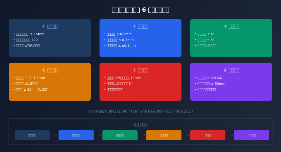
The hoisting mechanism is the core load-bearing component of a crane, and installation quality directly impacts overall safety and service life. This article systematically outlines the five critical parameter standards for hoist installation and commissioning — drum diameter-to-groove matching, axial float ≤ 0.5 mm, wire rope fleet angle ≤ 4°, brake clearance 0.5–1.5 mm, and static load test at 1.25 × rated load for 10 minutes with no abnormalities — along with fleet angle correction and acceptance criteria, providing a complete technical reference for field installation and inspection personnel.
Pre-Installation Checks for Hoisting Mechanisms
Before installing the hoisting mechanism, three fundamental verifications must be completed: foundation elevation deviation must not exceed ±5 mm, anchor bolt preload torque must meet design requirements, and shim plate coverage must be no less than 70% of the bearing area, with no more than three shims per group, all welded securely. In Kelude's standard installation procedure, the hoist base levelness is required to be ≤ 0.2 mm/m, measured with a frame spirit level at four quadrant points and averaged.
Upon unboxing, verify the completeness of technical documentation, including the Factory Certificate, Type Test Report, Operation Manual, and material certificates for major components. Per the GB/T 24816-2009 standard for crane hoist drums, the drum has already undergone static balance verification at the factory; on-site, re-check the drum surface for casting defects and confirm groove pitch deviation ≤ 0.5 mm.
Drum Installation Parameters and Inspection Methods
As the core component around which the wire rope wraps, the drum's installation accuracy directly determines rope service life and hoisting smoothness. According to the ISO 4301 Crane Design Standard, the ratio of the drum's nominal diameter to the wire rope diameter must satisfy: D ≥ h·d (h = 16 for work duty A1–A3, 18 for A4–A5, 20 for A6, and 25 for A7–A8), with groove radius R = (0.53–0.56)d and groove depth c ≥ 0.3d.
Five parameters require focused inspection during installation:
First, coaxiality between the drum shaft and the reducer output shaft must be ≤ φ0.1 mm, measured with a dial indicator at four points on the coupling outer diameter.
Second, axial float must be ≤ 0.5 mm, measured with a dial micrometer mounted on the drum end face.
Third, radial runout must be ≤ 0.3 mm, determined by slow rotation through 360° and recording the maximum reading.
Fourth, surface roughness of both groove sidewalls must be Ra ≤ 6.3 μm to prevent abrasion of the wire rope.
Fifth, rope clamp bolt tightening torque must be applied in 2–3 symmetrical passes to the design value.
Wire Rope Fleet Angle Correction Standards
The wire rope fleet angle is a critical parameter affecting hoist operating performance. Excessive fleet angle leads to wire rope derailment, accelerated abrasion, and in severe cases, rope tangling or even breakage. Per ISO 4309 Wire Rope Inspection Standard, the maximum allowable fleet angle relative to the drum groove centerline is 4°, and 5° for sheave rope grooves. On-site measurement uses a laser alignment tool or the string-line method, taken at three positions across the full drum travel (top limit, mid-travel, and bottom limit).
Three correction approaches apply when the fleet angle exceeds limits:
First, adjust the shim thickness under the drum bearing housing to alter the drum axis inclination, with each adjustment step not exceeding 0.5 mm, followed by re-checking coaxiality.
Second, install a rope guide or hold-down device, suitable for applications with lifting heights exceeding 30 m.
Third, increase the distance between the sheave and the drum, calculated using the empirical formula: L ≥ (W/2)/tan 4°, where W is the drum's effective winding width. Kelude's engineering team recommends at least 30 full-travel hoisting cycles under no load after correction to confirm the rope winds evenly without overlapping.
Static and Dynamic Load Test Acceptance Procedure
After installation, a graduated load test program must be carried out. Static load test: hoist 1.25 × rated load to a height of 100–200 mm above the ground and hold for 10 minutes, during which the drum, reducer, brake, and other critical components must show no permanent deformation or cracks, and main girder deflection must not exceed S/800 (S = span). After the test, lower to the ground and re-measure drum coaxiality and axial float; a deviation of ≤ 0.02 mm compared to pre-test readings is acceptable.
Dynamic load test: perform 5 full hoisting and lowering cycles at 1.1 × rated load, verifying that brake lowering distance ≤ 80 mm (at 1.25 × rated load), operating noise ≤ 85 dB(A), and bearing temperature rise ≤ 40 K. During the test, pay close attention to rope winding quality on the drum — cross-winding and abrupt gap changes are not permitted. After all tests are complete, record measured data, compile the installation and commissioning report, and file it for future reference.
Common Installation Issues and Troubleshooting
Three types of installation issues are most frequently encountered with hoisting mechanisms:
First, rope tangling, typically caused by excessive fleet angle or worn drum grooves. The troubleshooting sequence is: fleet angle → groove dimensions → rope clamp tension.
Second, excessive brake lowering distance, usually resulting from oversized brake clearance or oil contamination on the brake lining. The standard clearance of 0.5–1.5 mm must be verified point-by-point with a feeler gauge.
Third, abnormal noise and vibration during operation, which may stem from: coupling misalignment, improper reducer gear mesh clearance, poor drum dynamic balance, or loose anchor bolts.
Vibration testing uses a handheld vibration meter at three directions (horizontal, vertical, axial) on the bearing housing, with a vibration velocity RMS limit of ≤ 4.5 mm/s per ISO 10816-3. Kelude's after-sales team provides 48-hour on-site response service to ensure installation and commissioning issues are resolved promptly.
| Parameter Item | Standard Requirement | Detection Method |
|---|---|---|
| Coaxiality Deviation | ≤ φ0.1mm | dial indicator4Point-by-point method |
| Axial displacement | ≤ 0.5mm | dial micrometer End-face measurement |
| Radial Runout | ≤ 0.3mm | Barring (turning gear)360°Maximum value |
| Wire Rope Deflection angle | ≤ 4°(Drum) | Laser alignment/Wire-stretch method (string line method) |
| Brake Clearance | 0.5~1.5mm | Feeler gauge point-by-point check |
| Braking Drop (lowering amount) | ≤ 80mm | 1.25times Load Measured value |
6. Acceptance Standard Clause Comparison Table
| Acceptance Item | Corresponding Standard Clause | Assessment Indicator |
|---|---|---|
| drum diameter Ratio | ISO 4301 Crane Design Standard-2008 §5.4.2 | D/h·d ≥ 16~25 |
| Static load test | FEM 1.001 §4.2 | 1.25times/10min None Deformation |
| Wire Rope Scrap (condemn) | ISO 4309 Wire Rope Inspection Standard:2017 §5.3 | 6dWire breaks within a lay length≥5% |
| Drum Wall thickness | GB/T 24816 §4.3 | Casting≥12mm/Welding≥8mm |
| Vibration limit | ISO 10816-3 | ≤ 4.5mm/s rms |
| noise limit | FEM 1.001 §5.8 | ≤ 85dB(A) |
Key Installation Data for Hoisting Mechanisms
h=16~25
Drum Diameter Coefficient
≤4°
Max Wire Rope Fleet Angle
≤0.5mm
Axial Runout Limit
1.25×
Static Load Test Factor
≤80mm
Braking Drop Distance
≤85dB
Noise Limit During Operation
📖 Further Reading
ISO 4301 Crane Design Standard: 9 load combinations and A1~A8 work duty selection
ISO 16625:2020 Guide to Selection, Use and Maintenance of Wire Rope Drums and Pulleys for Cranes
Frequently Asked Questions
Q: What are the installation differences between cast drums and welded drums?
A: Cast drums (typically HT200 or QT450-10) have a minimum wall thickness of 12mm, offering higher dead weight and better vibration damping. They demand a more rigid foundation and more precise coaxiality adjustment during installation. Welded drums (Q345B or 16Mn) have a minimum wall thickness of 8mm, weigh 30%~40% less, and are easier to align on site — but they require full annealing after welding to relieve residual stress. Both types share the same groove accuracy requirements: pitch deviation ≤0.5mm and surface roughness Ra≤6.3μm. Kelude standardizes on welded drums for small and medium capacities (≤32t) and recommends cast drums for large capacities (≥50t).
Q: What are the specific wire rope fleet angle requirements under ISO 4301?
A: Clause 5.4.3 of ISO 4301 specifies that the maximum fleet angle of the wire rope in the drum groove (the angle between the rope centerline and the groove centerline) must not exceed 4°, and for multi-layer winding drums, 2°. The fleet angle at the pulley must not exceed 5°. If these limits are exceeded, corrective measures include increasing the drum-to-pulley spacing, adding a rope rewinding device, or optimizing the drum groove helix angle. In practice, we recommend keeping the angle within 3° for added safety margin; Kelude's factory standard is ≤2.5°.
Q: How do I quickly diagnose rope overlapping or stacking issues during trial run?
A: Follow this three-step diagnostic: First, check the fleet angle — use a laser alignment tool to verify the angle at three points across the full travel; if it exceeds 4°, adjust the drum support shims first. Second, inspect the drum groove — measure the groove pitch and depth with an optical flat and compare against the wire rope diameter; groove width should be (1.05~1.10)d. Third, check the rope clamp — confirm the tightening torque meets specification and that the clamp presses into the groove to a depth of at least 1/3 of the rope diameter. If all checks pass and the rope still overlaps, verify that the drum shaft and pulley shaft are parallel, with a parallelism deviation of ≤0.5mm/m.
Q: How much does it cost to complete installation and commissioning for a 5-ton electric hoist?
A: The installation and commissioning cost for a 5t electric hoist hoisting mechanism typically includes labor (2 workers × 1–1.5 days) at $180–$300, detector rental (dial indicator, spirit level, feeler gauge, etc.) at $45–$75, counterweight transport for the load test at $75–$120, and acceptance report preparation at $45–$75, totaling approximately $340–$560. Additional work such as drum replacement or skew correction adds $120–$220. Kelude's standard installation service covers all of the above, with one free re-commissioning visit during the warranty period. Final terms are subject to the signed technical service agreement.
