

Wire Rope Clip Installation Standards for Overhead Cranes
The orientation of wire rope clips (U-bolt direction) and their quantity are the two critical safety parameters for terminating wire ropes on overhead cranes.Per GB/T 5976-2006 Wire Rope Clips: use 3 clips for d≤20mm, 4 for 20<d≤32mm, 5 for 32<d≤40mm, and 6 for d>40mm; spacing at 6–7×d; the U-bolt must be installed on the dead (non-load-bearing) end of the rope; tightening torque ranges from 80 to 490 N·m depending on rope diameter.
Wire Rope Clip Orientation: Why U-Bolt Direction Is Critical
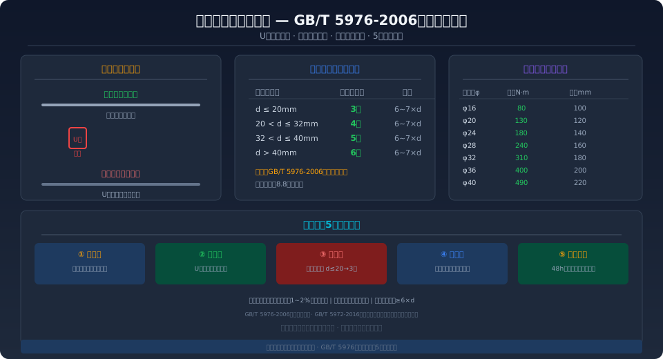
Clip orientation is the most overlooked yet consequential detail in wire rope end terminations. Per GB/T 5976-2006, the U-bolt must be placed on the dead end (non-load-bearing side) of the rope, with the saddle seated on the live end (load-bearing side). The engineering rationale: the U-bolt's curved base has minimal contact area with the rope. If installed on the live end, the contact points become stress risers under cyclic loading, accelerating wire breakage. The saddle's grooved surface, by contrast, conforms to the rope over a much larger arc (approx. 120°–140°), distributing clamping force evenly—making it suitable for the load-bearing side.
Two orientation errors are common in practice. The first: installing the U-bolt on the live end—this causes repeated bending of the load-bearing rope at the U-bolt's curved base. Kelude's engineering data shows that rope ends installed this way develop visible indentations and premature wire breaks within 2,000–5,000 duty cycles, achieving only 30%–40% of the service life of correctly installed terminations. The second: inconsistent clip orientation within a set—mixing forward and reverse clips creates uneven clamping force distribution, causing individual clips to loosen prematurely under overload. The correct practice is to orient all U-bolts uniformly toward the dead end, with the first clip positioned approximately 1.5–2×d from the rope end.
Wire Rope Clip Quantity: Scaled by Rope Diameter
Insufficient clip quantity is the leading cause of rope-end pullout failures. GB/T 5976-2006 specifies four minimum clip-count tiers based on wire rope diameter: 3 clips for d≤20mm, 4 for 20<d≤32mm, 5 for 32<d≤40mm, and 6 for d>40mm, with uniform spacing of 6–7×d (d = nominal rope diameter). Kelude applies a stricter in-house manufacturing standard: a minimum of 4 clips for d≤20mm and 5 clips for d>20mm—one more than the national standard in each tier—to ensure reliable rope-end connections on cranes with higher work duty classifications (A5~A8) subject to frequent starts and impact loads.
For example, a common electric hoist using φ16mm wire rope: the national standard requires 3 clips at 100mm spacing; Kelude's standard requires 4 clips at 100mm spacing. For a QD Type double-girder bridge crane using φ28mm wire rope: the national standard requires 4 clips at 160mm spacing; Kelude's standard requires 5 clips at 160mm spacing. The additional clips effectively distribute the clamping force gradient across the termination, reducing local stress on each clip by approximately 15%–20%.
| wire rope diameterd(mm) | GB/T 5976Minimum Number of Wire Rope Clips | Kelude Manufactured Standard | Wire Rope Clip Spacing(mm) | Typical Applicable Crane Models |
|---|---|---|---|---|
| d ≤ 20 | 3pcs | ≥4pcs | 6~7×d | CD1/MD1Electric Hoist, LD Type Single Girder |
| 20 < d ≤ 32 | 4pcs | ≥5pcs | 6~7×d | LH Type Hoistdouble girder, QD Type20t |
| 32 < d ≤ 40 | 5pcs | ≥6pcs | 6~7×d | QD Type32~50t, MG Type Gantry |
| d > 40 | 6pcs | ≥7pcs | 6~7×d | QD Type≥75t, YZMetallurgical Type |
Wire Rope Clip Tightening Torque Chart
The tightening torque applied to wire rope clip bolts directly determines the reliability of the grip. Insufficient torque allows the wire rope to slip under load, causing the rope end to progressively shorten and eventually pull free. Excessive torque overstresses the bolt, leading to fatigue fracture under cyclic loading. ISO 4301 specifies standard torque values based on wire rope diameter, and all field installations must be performed using a torque wrench for precise control—never tighten by feel.
| wire rope diameter(mm) | Wire Rope Clip Specification | tightening torque(N·m) | Clip Saddle Spacing(mm) | Bolt Grade |
|---|---|---|---|---|
| φ16 | 16 | 80 | 100 | 8.8Grade |
| φ20 | 20 | 130 | 120 | 8.8Grade |
| φ24 | 24 | 180 | 140 | 8.8Grade |
| φ28 | 28 | 240 | 160 | 8.8Grade |
| φ32 | 32 | 310 | 180 | 8.8Grade |
| φ36 | 36 | 400 | 200 | 8.8Grade |
| φ40 | 40 | 490 | 220 | 8.8Grade |
Wire Rope Clip Installation: 5-Step Inspection Procedure
Installing wire rope clips is not a rough "thread it through and tighten it" operation—it's a technical process that demands item-by-item verification. Below is the 5-step inspection procedure compiled by Kelude Heavy Industry's engineering department. Each step has clear acceptance criteria and required tools:
Step 1: Select the Correct Clip Size — Match the Clip to the Wire Rope Diameter — Measure the wire rope's nominal diameter with a vernier caliper (take the average of 3 readings on an unworn section), then select the clip size that matches the measured diameter. The clip size must correspond exactly to the wire rope diameter (e.g., a φ16 rope requires a size-16 clip). Never substitute a larger or smaller clip. The radius of the saddle's curved groove should be R=(0.53~0.55)×d to ensure full contact with the rope surface.
Step 2: Set the Orientation — U-Bolt Goes on the Dead (Short) End — First, form an eye by passing the wire rope around the hook or wedge socket. Identify the live end (load-bearing side, running to the drum) and the dead end (non-load-bearing side, the tail return). All U-bolts must be placed on the dead end, with the saddle on the live end. Install the first clip at a distance of approximately 1.5~2×d from the rope end, leaving sufficient tail length (≥6×d).
Step 3: Determine the Quantity — Minimum Number of Clips per Diameter — Refer to the GB/T 5976-2006 standard table to determine the minimum number of clips required for the rope diameter. Kelude Heavy Industry recommends adding one extra clip as a safety margin. Space the clips uniformly at 6~7×d (e.g., for a φ28 rope, spacing is 168~196mm). Use a steel tape measure to mark the clip positions at equal intervals.
Step 4: Apply the Correct Torque — Tighten in Two Stages with a Torque Wrench — For clips using 8.8-grade high-strength bolts, set the torque wrench according to the torque specification table. Tighten in two stages: first to 60%~70% of the target torque to seat all clips evenly, then tighten alternately and symmetrically to 100% of the target torque. Start from the clip closest to the eye and work outward. After full tightening, use a 0.02mm feeler gauge to check between the saddle and the rope—the gauge must not penetrate for a pass.
Step 5: Re-Tighten — Check After Pre-Stretching and Again After 48 Hours — After installing a new rope, apply a pre-stretch load of approximately 10% of the breaking force (hold for 10~15 minutes to eliminate structural elongation). The rope diameter will shrink by about 1%~2%, so all clips must be re-checked and re-tightened with a torque wrench. Perform a full re-tightening inspection 48 hours after initial service, then include it in the weekly inspection routine. If any single clip bolt shows signs of loosening during daily inspection, re-tighten the entire set rather than just the loose one.
Common Wire Rope Clip Installation Mistakes and Their Consequences
In field practice, wire rope clip installation errors fall into three categories: orientation, quantity, and tightening. Listed below from most to least frequent, with specific engineering consequences for each:
U-Bolt Installed on the Live End (≈35% of cases) — The U-bolt is placed on the load-bearing side (live end) with the saddle on the dead end. Consequence: the live rope is repeatedly bent around the U-bolt's curved base, creating stress concentration that produces visible indentations after 2,000~5,000 duty cycles and reduces rope service life by 60%~70%. The correct procedure is detailed in Step 2 above.
Insufficient Number of Clips (≈25% of cases) — For example, using only 2~3 clips on a φ24 rope instead of the 4 required by standard. Consequence: each clip carries more tension than its design value. The first clip (which bears approximately 70% of the total load) experiences bolt stress beyond limits, gradually loosening after 500~1,000 cycles until the rope end slips out of the clips. In crane rope-end pullout accidents in China from 2008 to 2023, approximately 45% were directly caused by insufficient clip quantity.
Incorrect Tightening Torque — Too Low or Too High (≈20% of cases) — Skipping the torque wrench and tightening by feel. Insufficient torque causes the rope to slip under load as clamping force is lost; excessive torque leads to fatigue fracture of the bolts under alternating loads. A φ28 rope clip bolt requires 240N·m of torque—equivalent to applying roughly 80kg of force on a 300mm wrench—which is virtually impossible to judge accurately by feel alone.
Uneven Clip Spacing or Improper First Clip Position (≈15% of cases) — Excessive spacing creates bending segments between clips, interrupting clamping force; insufficient spacing causes overlapping clamping effects that render the middle clips ineffective. If the first clip is too close to the rope end ( (<1×d), the tail may pull out; if too far, it wastes rope length and affects the eye dimensions.
Further Reading
Wire rope clip installation is just one part of wire rope safety management. A complete safety management chain also includes daily inspection, periodic non-destructive testing, and discard criteria. For more information, see our articles on GB/T 5972-2016 "Cranes — Wire ropes — Care and maintenance, inspection and discard" and GB/T 5976-2006 "Wire rope clips". For general crane safety requirements, refer to GB/T 6067.1 "Safety rules for lifting appliances".
Frequently Asked Questions
Q: Why must the U-bolt of a wire rope clip be placed on the dead end? What happens if it's reversed?
A: Per GB/T 5976-2006, the U-bolt's curved base has a small contact area with the rope (line contact). When placed on the live end, it creates stress concentration under alternating loads, causing premature wire breakage after 2,000~5,000 cycles—reducing service life to just 30%~40% of what correct installation achieves. Kelude Heavy Industry classifies this as a mandatory A-class inspection item in our factory acceptance test.
Q: How many clips are needed for a φ28 wire rope, and what should the spacing be?
A: GB/T 5976-2006 specifies a minimum of 4 clips for ropes with 20<d≤32mm, with spacing of 6~7×d (168~196mm) and a tightening torque of 240N·m. Kelude Heavy Industry's manufacturing standard adds one extra clip (5 total) to ensure rope-end reliability on cranes with A5~A8 work duty classifications under frequent start-stop operation and impact loads. The bolts are 8.8-grade high-strength bolts, tightened precisely with a torque wrench.
Q: Why do new wire rope clips need re-tightening after installation, and how soon?
A: New wire rope undergoes structural elongation under initial load (eliminating gaps between strands and wires), reducing the diameter by about 1%~2% and causing a drop in clip preload. Therefore, after installation, apply a pre-stretch at approximately 10% of the breaking force for 10~15 minutes, then immediately re-tighten all clips with a torque wrench. Re-check the tightening status 48 hours after initial service. Thereafter, include this in the weekly inspection routine, using a 0.02mm feeler gauge to check the gap between the saddle and the rope.
Q: If one clip bolt loosens, can I just tighten that single one?
A: No. The clip set functions as an integrated clamping system—each clip shares the load in sequence, with the first clip bearing approximately 70% of the total tension. When a single bolt loosens, it indicates the entire clamping force distribution has become unbalanced. The correct approach is to use a torque wrench to re-tighten all bolts in the set, starting from the first clip nearest the eye and working outward at the standard torque value. Kelude Heavy Industry's factory acceptance test procedure requires a full 0.02mm feeler gauge check on all clips after re-tightening—penetration at any point constitutes a failure.
