

Overhead Crane Load Limiter Calibration: 3-Point Method
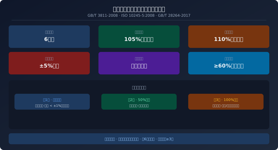
Load limiters on bridge cranes must be calibrated every 6 months using the three-point calibration method with standard test weights (zero, 50%, and 100% of measuring range). The alarm threshold is set at 105% of rated load, with automatic cut-off at 110%. Accuracy must be within ±5%, and calibration records must be retained for at least 3 years.
The lifting capacity limiter is the core safety device in a crane's protection system. Under the mandatory requirements of ISO 4301 (Crane Design Standard) and ISO 12480 (Safety Code for Lifting Appliances), every bridge crane must be equipped with a functioning load limiter. The calibration interval, method, and accuracy verification directly affect lifting safety. This article breaks down the subject from five angles: applicable standards, calibration intervals, the three-point procedure, error acceptance criteria, and routine maintenance.
Calibration Interval and Applicable Standards
Industry standards set clear requirements for load limiter calibration intervals. Per GB/T 28264 Safety Monitoring and Management System and ISO 10245-5:2008 (Limiters and Indicators for Bridge and Gantry Cranes), limiters must be calibrated every 6 months. Immediate recalibration is required under the following conditions: after replacing a sensor or display unit, after a severe overload event (exceeding 110% of rated load), or after a major overhaul or structural retrofit.
Calibration records must be kept in full compliance with the applicable standard, including the calibration date, technician name, test weight identification numbers and mass values, sensor output and displayed readings at each calibration point, calculated error values, and the pass/fail conclusion. Per ISO 4301, records must be retained for at least 3 years for review during annual inspections by the special equipment inspection authority. For heavy-duty cranes in work duty classifications A6 through A8, Kelude recommends shortening the calibration interval to 3–4 months to mitigate sensor drift caused by high-frequency operation.
Three-Point Calibration Procedure Step by Step
The three-point calibration method is the standard approach for load limiter verification. By loading at zero, mid-range, and full-scale points, it provides a comprehensive assessment of sensor linearity, repeatability, and accuracy. Here is the step-by-step procedure:
Step 1 — Zero Calibration. With the crane unloaded (lifting spreader resting on the ground, wire rope slack), observe the limiter display and confirm the reading returns to zero. Zero deviation must be within ±1% of the rated lifting capacity. If zero drift exceeds this range, adjust using the internal zero potentiometer or software parameters, then wait 2 minutes and re-check that the reading remains stable.
Step 2 — 50% Range Calibration. Load the crane to 50% of rated lifting capacity using standard test weights. During progressive loading, record the sensor output (mV signal or 4–20 mA) and the displayed value at every 10% increment of the measuring range. Calculate linearity error at each point: Error (%) = (Displayed Value − Actual Load) ÷ Rated Lifting Capacity × 100%. Deviation must be ≤ ±5%.
Step 3 — 100% Range Calibration. Load to rated lifting capacity, hold for 10 seconds, and record the displayed value. Error must be ≤ ±5%. Continue loading slowly to 105% of rated load and verify that the limiter activates the audible and visual alarm (pre-warning function). Continue to 110% of rated load and verify that the limiter automatically cuts off the hoisting power circuit (power-off protection). After cut-off, confirm that the hoisting mechanism cannot be restarted until a manual reset is performed.
Step 4 — Return Stroke Verification. Unload gradually from 100% of the measuring range back to zero, recording readings at every 20% decrement. Compare the loading and unloading curves; hysteresis error must be ≤ ±3%. If hysteresis exceeds the limit, inspect the sensor's elastic element for residual deformation and check whether contact resistance in the signal cable path is abnormally high.
Error Acceptance Criteria and Sensor Diagnostics
After calibration, each calibration point is judged as pass or fail based on its error value. The sensor's combined error must simultaneously satisfy three criteria: linearity error ≤ ±5% FS (full scale), repeatability error ≤ ±3% FS, and hysteresis error ≤ ±3% FS. If any of the three fails, first inspect the signal path — check the sensor shield grounding resistance (should be < 4 Ω), check terminal blocks for oxidation or loose connections, and check the junction box for moisture ingress.
If errors remain out of tolerance after the wiring inspection, test the sensor individually. Use a multimeter to measure the sensor bridge resistance (typically 350 Ω ± 5 Ω or 700 Ω ± 10 Ω, depending on model). With an excitation voltage of 5–12 V DC, verify the full-scale output signal (typically 1–2 mV/V). Replace the sensor if zero drift exceeds ±2% FS per year or if the output signal attenuates by more than 10%. Standard bridge crane configurations use the QCX-M panel-mount limiter or the SY-2 digital display limiter, with sensors rated IP65 and an operating temperature range of −20 °C to +60 °C.
Calibration Parameter Reference by Capacity
When calibrating bridge cranes of different rated lifting capacities, pay close attention to test weight configuration and measuring range correspondence. The table below lists calibration parameters for common capacity ratings:
| Rated Lifting Capacity | Test Weight at 50% Load | Test Weight at 100% Load | Alarm Trigger (105%) | Cut-Off Trigger (110%) |
|---|---|---|---|---|
| 5 t | 2.5 t | 5 t | 5.25 t | 5.5 t |
| 10 t | 5 t | 10 t | 10.5 t | 11 t |
| 16 t | 8 t | 16 t | 16.8 t | 17.6 t |
| 20 t | 10 t | 20 t | 21 t | 22 t |
| 32 t | 16 t | 32 t | 33.6 t | 35.2 t |
| 50 t | 25 t | 50 t | 52.5 t | 55 t |
Note: All values above are in metric tons. For cranes rated in short tons (US), convert accordingly (1 short ton = 0.907 metric tons) and select test weights that match the corresponding metric equivalent.
Routine Maintenance and Daily Checks
In addition to periodic calibration, daily inspections help ensure the load limiter remains accurate and reliable between calibration intervals. Operators should perform the following checks before each shift:
- Verify the display unit powers on normally and shows zero with no load on the hook.
- Confirm the sensor cable and junction box show no signs of damage, abrasion, or moisture.
- Test the audible and visual alarm by lifting a known load to verify the alarm activates at the correct threshold.
- Check that all terminal block connections are tight and free of corrosion.
- Ensure the limiter's protection rating (IP) is maintained — replace damaged gaskets or covers immediately.
If any abnormality is detected during daily checks, the crane must be taken out of service until the issue is diagnosed and resolved. Do not operate the crane with a suspected faulty load limiter, regardless of how minor the issue appears.
Common Calibration Issues and Troubleshooting
Even with proper calibration procedures, issues can arise. The table below summarizes common problems, their likely causes, and recommended corrective actions:
| Symptom | Likely Cause | Corrective Action |
|---|---|---|
| Display shows non-zero reading with no load | Zero drift; sensor elastic element deformation | Perform zero calibration; if drift persists, test sensor individually |
| Readings fluctuate erratically during lifting | Loose signal cable connection; shield grounding issue | Tighten terminal blocks; verify grounding resistance < 4 Ω |
| Alarm triggers below 105% of rated load | Incorrect calibration; sensor output drift | Re-calibrate; replace sensor if output attenuation exceeds 10% |
| No alarm at 105% or cut-off at 110% | Faulty relay or contactor; limiter internal fault | Inspect control circuit; test limiter output; replace if defective |
| Error exceeds ±5% at all calibration points | Sensor overload damage; signal cable damage | Replace sensor; inspect and replace signal cable if necessary |
For persistent issues that cannot be resolved through the steps above, contact the crane manufacturer or a qualified service provider for a full system diagnosis. Do not attempt to bypass or disable the load limiter under any circumstances.
FAQ: Load Limiter Calibration Questions
Q: How often should a bridge crane load limiter be calibrated?
A: The standard calibration interval is every 6 months. However, immediate recalibration is required after sensor replacement, a severe overload event (above 110% of rated load), or a major overhaul/structural modification. For heavy-duty cranes in high work duty classifications, Kelude recommends a shorter interval of 3–4 months.
Q: What is the three-point calibration method?
A: The three-point method involves loading the crane at zero, 50%, and 100% of the rated lifting capacity using certified standard test weights. At each point, the sensor output and displayed value are recorded and compared. The 105% and 110% overload points are also verified to confirm alarm and cut-off functions operate correctly.
Q: What accuracy is required for a load limiter after calibration?
A: The combined error must meet three criteria simultaneously: linearity error ≤ ±5% FS, repeatability error ≤ ±3% FS, and hysteresis error ≤ ±3% FS. If any of these is exceeded, the cause must be investigated and corrected before the crane is returned to service.
Q: How long must calibration records be kept?
A: Calibration records must be retained for at least 3 years. Records should include the calibration date, technician name, test weight identification and mass values, sensor output and displayed readings at each point, calculated errors, and the final pass/fail determination.
Q: Can I calibrate the load limiter myself?
A: Calibration should only be performed by qualified personnel with access to certified standard test weights and proper test equipment. While daily checks can be performed by operators, full three-point calibration requires specialized knowledge and equipment to ensure accuracy and compliance with safety standards.
| Rated Lifting Capacity | Test Weightminimum Quality | 105%Alarm Point | 110%Cut-off Point | Permissible Tolerance Range |
|---|---|---|---|---|
| 5t | ≥3t | 5.25t | 5.50t | ±0.25t |
| 10t | ≥6t | 10.50t | 11.00t | ±0.50t |
| 16t | ≥9.6t | 16.80t | 17.60t | ±0.80t |
| 20t | ≥12t | 21.00t | 22.00t | ±1.00t |
| 32t | ≥19.2t | 33.60t | 35.20t | ±1.60t |
| 50t | ≥30t | 52.50t | 55.00t | ±2.50t |
Calibration Tools and Test Weight Requirements
A: Calibrating a lifting capacity limiter imposes specific requirements on the quantity and accuracy of test weights. The total mass of standard weights must be no less than 60% of the limiter's maximum measuring range, with an accuracy grade of at least M1 per OIML R111. For a 5t crane, a minimum of 3t of standard weights is required (e.g., 30 pieces × 100kg or 15 pieces × 200kg); for a 32t crane, at least 19.2t of weights is needed. Test weights must be recalibrated at a certified facility at intervals not exceeding 12 months.
Supporting calibration tools include a high-precision digital multimeter (0.01mV resolution for measuring sensor bridge output), a standard signal source (to simulate 4~20mA current loop signals for verifying display channels), and an insulation resistance tester (500V megohmmeter, verifying sensor-to-ground insulation ≥20MΩ). For wireless limiter systems, check RF signal strength (RSSI ≥ -75dBm) and data packet loss (≤1%). A FLUKE 754 process calibrator is used during calibration to simulate and record sensor signals, ensuring full traceability of calibration data.
Common Calibration Issues and Troubleshooting
Three types of problems are most frequently encountered during calibration and require targeted diagnosis:
Erratic or unstable display readings — Poor shielding ground on the sensor signal cable is the primary cause. Measure the shield-to-ground resistance with a megohmmeter; it should be <4Ω. Also inspect the junction box for moisture ingress — open it, dry with a heat gun, and replace the desiccant. If fluctuation persists, use an oscilloscope to check the sensor output waveform and rule out VFD harmonic interference (install a ferrite filter on the sensor signal cable if necessary).
Excessive deviation at alarm trip points — The limiter fails to alarm at 105% load or triggers prematurely at 98%. First verify the actual mass of the test weights (weights may lose mass due to wear over time), then check the alarm threshold parameters in the limiter's instrument. For analog limiters, adjust the corresponding potentiometer and lock it in place; for digital units, correct the thresholds in the parameter setup menu, save, and reboot.
Overload cut-off function failure — This is the most serious safety hazard. If the hoisting mechanism does not cut power when loaded to 110% of rated load, stop calibration immediately and inspect the contactor or relay control circuit. Common causes: welded relay contacts or an open relay coil circuit. Use the continuity mode on a multimeter to test each normally-closed relay contact in the control loop, confirming that the trip signal reaches the main contactor coil of the hoist.
| Fault Symptom | Possible Cause | Detection Method | Corrective Action |
|---|---|---|---|
| Continuous Display Fluctuation | Shielded Wire Grounding Defective | Megohmmeter (Insulation Tester)Measure to Ground Resistance | Ensure<4Ω, Add Ferrite Core Filter |
| Zero Drift>2%FS | Sensor Elasticity Creep | Compare with Historical Data Calibration Data | Zero Drift>±2%FS/Replace Annually Sensor |
| Linearity Error>5% | Sensor Overload Damage | Measuring Bridge Circuit Resistance Value | Bridge Open Circuit or Resistance Deviation>5ΩReplace with New |
| Exceed110%Without Power Interruption | Control Relay Contact Welding/Sticking | multimeter Continuity Measurement | Replace Annually Relay, Testing Interlock Circuit |
| Instrument Display Err/OL | sensor signal Wire Break | Continuity Measurement4~20mAInterlock Circuit Current | Troubleshooting Junction box Terminal, Re-crimp |
Load Limiter Calibration: Common Questions & Expert Answers
Q: Can the calibration interval for a lifting capacity limiter be extended to one year?
A: Extending the interval is not recommended. Per the technical requirements of GB/T 28264-2017 and ISO 10245-5:2008, the calibration interval for a lifting capacity limiter is 6 months. The sensor elastomer is subject to creep and zero-drift under prolonged alternating loads; over a year, zero drift can accumulate to 3%–5% FS, causing the 105% alarm and 110% cut-off thresholds to shift. For heavy-duty bridge cranes rated A6 to A8, Kelude recommends shortening the calibration interval to 3–4 months.
Q: How do you calibrate a crane when sufficient test weights are not available (e.g., for a 50t crane)?
A: For large-capacity cranes, an alternative loading method can be used: a hydraulic loading device paired with a reference-grade force sensor (accuracy class 0.1) serves as the standard, applying calibration force in increments while recording the limiter readings. The force uncertainty of the alternative loading device should be ≤ ±2%, and the device must be sent for metrological verification annually. A segmented test-weight method is also an option: first use a truck scale to calibrate several heavy objects as temporary test weights, then load them progressively to complete a three-point calibration.
Q: For bridge crane load limiters, what is the difference between single-sensor and dual-sensor wiring configurations?
A: The single-sensor configuration suits applications where load is carried by a single wire rope or where the lifting spreader is centrally symmetric; the sensor is mounted on the pulley shaft of the fixed sheave or the equalizer sheave. The dual-sensor configuration is for applications with two or four ropes where loading is asymmetric; the two sensors measure tension on each side independently and the readings are summed. For dual-sensor calibration, each channel must be calibrated separately, then the combined error of the summed value is verified. During wiring, pay attention to the sensor excitation voltage (5–12V DC) and signal polarity—reversed polarity will cause negative readings.
Q: Are the load limiters on Kelude bridge cranes calibrated before shipment? How does periodic verification work afterward?
A: Kelude bridge cranes undergo a three-point calibration of the lifting capacity limiter and full verification of alarm/shut-off functions before leaving the factory. A calibration certificate and original calibration records are included with the equipment. After installation and commissioning on site, an adaptive calibration is performed to compensate for any zero-point shift that may have occurred during transport. Subsequent 6-month periodic verifications can be carried out by the Kelude after-sales team or by a qualified third-party inspection authority. After calibration, a calibration label (showing the calibration date and next due date) must be affixed next to the limiter indicator.
Further Reading: Understanding GB/T 28264-2017 Safety Monitoring and Management System for Lifting Appliances · ISO 10245-5:2008 Standard for Limiters and Indicators on Bridge and Gantry Cranes
Kelude Heavy Industry maintains a full set of load limiter calibration equipment and certified calibration personnel, offering calibration services for bridge cranes, gantry cranes, metallurgical cranes, and explosion-proof models. All calibration data is traceable to national metrological standards, and calibration certificates meet the requirements for annual inspection by special equipment inspection authorities.
