

Crane Drum Rope Groove Wear: Detection, Repair & Scrapping Criteria
📋 Key Summary
Unaddressed wear on crane drum grooves destabilizes wire rope spooling and accelerates bidirectional damage between the rope and the groove. On-site inspections must focus on remaining wall thickness at the groove bottom, changes in the groove radius, and surface cracks. For example, in a European Standard double-girder crane with a 50t capacity, scrapping procedures should typically be initiated when groove depth loss reaches 40% of the original design or when the measured wall thickness drops below 60% of the design value. If machining is performed to restore the profile, the remaining wall thickness must not fall below 65% of the nominal drum thickness, and pitch deviation must be controlled within 0.3mm.
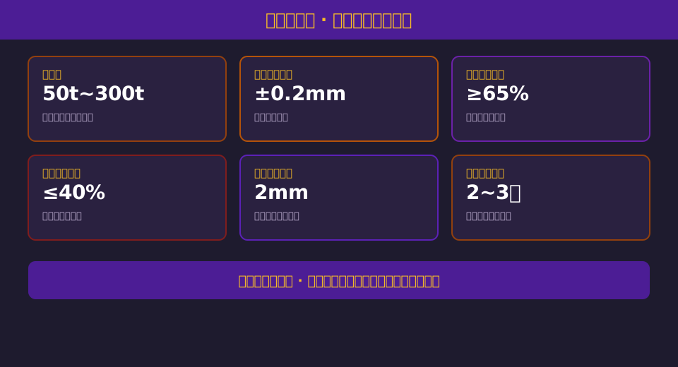
In the after-sales and maintenance system of Kelude Heavy Industry, diagnosing drum groove wear is a mandatory inspection item before mid-term repairs or overhauls for overhead and gantry cranes. Because crane drums are expensive and have long replacement intervals, field personnel often focus solely on wire rope wear while overlooking how geometric changes in the groove profile amplify stress on the rope. According to the matching principles for drums and wire ropes outlined in FEM 1.001 (Crane Design Specification), the ratio between groove pitch, drum diameter, and wire rope diameter directly determines the bending fatigue and compression state of the wire rope. Once this balance is lost, upstream reducers, couplings, and downstream hook blocks are all subjected to additional loads. This article provides actionable methods across three levels: detection, repair, and discard criteria.
Kelude Heavy Industry employs groove profiles verified through multiple profile modifications in its European Standard double-girder products ranging from 50t to 300t. Factory accuracy ensures groove pitch deviation remains under 0.2mm. However, under long-term heavy-load and swinging operating conditions, users must still conduct periodic inspections on-site. In accordance with the requirements of the TSG 51-2023 Crane Safety Technical Supervision Regulation, the crane drum is classified as a primary load-bearing component affecting the safety performance of lifting appliances; therefore, wall thinning and surface defects must be included in the user unit's daily inspection records. The following details are broken down into four dimensions.
On-Site Measurement Methods for Drum Groove Wear and Gauge Correction
Field inspections begin by establishing reference planes. The machined surfaces of the bearing housings at both ends of the drum, or the un-worn flanges of the rope grooves, can serve as axial references, while the un-contacted outer cylinder area serves as a radial reference. Do not use areas where the wire rope has been pressed and abraded for an extended period as references, as this will result in systematically low readings.
Step 1: Use a vernier caliper with 0.02mm precision to measure the remaining thickness from the groove bottom to the drum's outer cylinder. Take one measurement point every 90°, ensuring no fewer than 4 points per single groove.
Step 2: Insert a groove template gauge into the groove bottom to observe light leakage gaps. If the groove bottom radius exceeds the original design radius by more than 0.5mm, the groove shape has widened, causing the wire rope to slide toward the sides.
Step 3: Measure the groove spacing. Span 10 rope grooves, measure the total length, and divide by 10 to correct for single-pitch measurement errors. If the measured pitch deviates from the design value by more than 0.3mm, uneven hoist winch speed and a significantly higher probability of rope entanglement will occur.
According to Kelude Heavy Industry maintenance records, a 75t European Standard double-girder crane had a designed groove pitch of 22mm. The average pitch for grooves 1–10 was measured at 21.62mm (deviation: -0.38mm), while the average for grooves 40–50 was 22.41mm (deviation: +0.41mm). Cumulative axial error caused the wire rope to climb at groove 42, triggering two rope entanglement alarms within three days. Measurement readings are not isolated values for a single groove but represent cumulative differences along the axial direction of the drum shell.
For drums still in use where the inner wall cannot be directly measured, an ultrasonic thickness gauge can be used to scan corresponding positions on the outer cylinder relative to the groove bottoms. Ensure the surface roughness is lower than Ra12.5 and that coupling agent is applied evenly; otherwise, sound wave attenuation may lead to inflated readings. Retain 8–12 measurement points per inspection to generate a remaining wall thickness curve.
Allowable Stock Calculation for Groove Turning and Control of Surface Parameters
The core logic of turning repair is to restore the groove profile and pitch while ensuring the drum shell retains sufficient strength. Remaining wall thickness must be calculated prior to machining.
Engineering Example: For a European Standard double-girder drum rated at 100t, with a nominal outer diameter of 820mm and a nominal wall thickness of 45mm. In the worn area, the single-side groove depth increased by 6.2mm. A preliminary estimate of the remaining wall thickness after wear is 45 - 6.2 = 38.8mm. Based on Kelude Heavy Industry maintenance standards, the remaining wall thickness after turning must not be less than 65% of the nominal thickness, i.e., 45 × 0.65 = 29.25mm. If a planned turning amount of 3.5mm is required to restore the profile, the final remaining wall thickness would be 38.8 - 3.5 = 35.3mm. Since 35.3mm is greater than 29.25mm, the turning plan is executable. If the remaining thickness falls below 29.25mm after accounting for wear and turning, turning is prohibited, and the scrapping process is initiated.
Calculations should not just provide conclusions but show the work for field personnel: Remaining Wall Thickness = Measured Average Drum Wall Thickness - Turning Depth at that Groove Position. Wall thickness varies at internal reinforcement rings; use the thinnest cross-section as the benchmark for judgment.
Regarding turning parameters, control the finishing cutting speed at 60~80m/min and feed rate at 0.1~0.15mm/r. The surface roughness at the groove bottom should reach Ra3.2, and the groove side surface should reach Ra6.3. If roughness exceeds these values, the friction coefficient between the wire rope and the groove wall increases, accelerating wear on the outer surface of the wire rope strands.
After turning, each groove must be inspected individually using a groove template. On any single drum, the pitch deviation between any two adjacent rope grooves must not exceed 0.2mm, and the cumulative deviation for any 20 grooves must not exceed 0.8mm. Exceeding this range causes the wire rope to axially migrate due to uneven spacing, even if the groove profile is smooth.
Wall Thickness Thresholds and Crack Grading for Drum Scrapping Criteria
Drum scrapping criteria cannot rely solely on groove wear; they must also consider the remaining strength of the drum body. The following threshold values are commonly used in Kelude Heavy Industry field operations and are applicable to the European Standard double-girder series rated from 50t to 300t. Specific limits are subject to the actual contract technical annexes.
| Inspection Criteria | Monitor / Continue Observation | Use After Repair | Directscrapping |
|---|---|---|---|
| Remainingwall thicknessRatio | ≥75% | 65%~75% | <65% |
| Root of GrooveWearIncrement | <Originalgroove depth 25% | 25%~40% | >40% or Groove Distortion |
| SurfaceCrack | None | Single Non-Penetrating,Depth<2mm | Penetrating or Clustered |
| rope groovePitchDeviation | ≤0.2mm | 0.2~0.45mm TurningRestore | >0.5mm and UnableTurning |
Distinguishing between hot cracks and fatigue cracks is essential for accurate assessment. Hot cracks typically appear in the heat-affected zone (HAZ) of the drum shell flange welds, exhibiting a radial pattern. If grinding reveals a depth exceeding 3mm, repair welding is not recommended; the component should be taken out of service. Fatigue cracks usually propagate circumferentially along the root of the rope groove. If a single crack exceeds 25mm in length or if three or more short cracks appear on the same cross-section, operations must cease immediately pending a technical evaluation.
Drum deformation also requires close attention. If the end-runout exceeds 0.5mm during measurement, accompanied by abnormal noise at low speeds and increased amplitude at high speeds, first rule out loose bearing housings before determining if the drum shell has suffered permanent bending. Any attempt to straighten the drum via hammering is strictly prohibited; scrapping is the only option.
Kelude Heavy Industry recommends adding offline laser scanning for select large tonnage projects. By comparing the 3D point cloud of the rope grooves against factory baseline data, deviations exceeding ±0.5mm continuously across 30% of the groove length indicate that wear has progressed from isolated points to regional profile failure.
No-Load Trial Run Procedures and In-Service Data Management After Drum Repair
Drums repaired via turning or local grinding cannot be immediately put into heavy load service. They must undergo no-load and stepwise load tests first. Perform 12 forward and reverse cycles with a stroke of at least 5m per cycle, observing whether rope spooling is neat and checking for jumping out of the groove. Subsequently, run at 50% rated load for 30 minutes, then at 80% rated load for 20 minutes, recording current, temperature rise, and noise throughout.
Regarding data management, each inspection record must include at least six fields: measurement point location, remaining wall thickness, pitch deviation, surface crack status, lubrication status, and recommendations. Missing any category prevents subsequent trend analysis. Kelude Heavy Industry’s after-sales team advises establishing a drum file on a 3-month cycle for users, reducing this interval to 2 months for cranes with an operating time exceeding 2,000 hours annually.
Rope groove wear rate is strongly correlated with wire rope tension fluctuations. If the wear amount difference between the two ends of the same drum exceeds 0.8mm, check for angular misalignment between the fixed pulley block axis and the drum shaft axis. For every 0.5° increase in this angle, the lateral force component of the wire rope against the groove wall increases by approximately 0.87% of the corresponding tension value. Calculating for a 100t load with a single rope tension of 65kN, a 2° misalignment results in a lateral force of roughly 65 × sin(2°) ≈ 2.27kN. Although this force seems small, its long-term action on the groove edge is sufficient to deepen the profile on one side.
The wire rope used in conjunction with the drum must be evaluated simultaneously. If the measured wire rope diameter falls below 93% of the nominal diameter, or if wire breaks are concentrated in one strand with more than five breaks within one lay length, replace the rope first before re-inspecting the rope groove. Old ropes can mask the true wear condition of the groove; replacing them often exposes underlying issues with the drum itself.
Related reading: On-Site Setting and Verification of Anti-Collision Safety Distance for Cranes, Application Boundaries of AI Anti-Sway Algorithms in European Standard Double-Girder Cranes, Weld Crack Detection and Graded Maintenance Plans for Main Girders. These issues often arise within the same lifecycle as drum wear and can be troubleshooted together.
When delivering 50t~300t European Standard Double-Girder products, Kelude Heavy Industry hands over initial rope groove parameters and remaining wall thickness data as Documentation Included. Any subsequent turning, repair welding, or adjustment must update this original archive synchronously; otherwise, discard criteria assessments will become inaccurate due to missing baselines.
Frequently Asked Questions
Q: At what millimeter threshold of rope groove wear must the drum be scrapped?
A: Do not rely solely on unilateral millimeter measurements; assess based on nominal wall thickness. Enter the discard criteria process when the remaining wall thickness at the groove bottom falls below 65% of the original design thickness or when the wear increment exceeds 40% of the original groove depth.
Q: What is the appropriate surface roughness after drum turning?
A: The groove bottom should ideally be Ra3.2, and the groove sides Ra6.3. Control the cutting speed at 60~80m/min and feed rate at 0.1~0.15mm/r. Excessive roughness accelerates wear on the outer surface of the wire rope.
Q: Can a drum with surface cracks be repaired via welding and continue in service?
A: Single non-penetrating cracks less than 2mm deep can be ground and monitored. Cracks deeper than 3mm, clustered multiple cracks, or penetrating cracks should not be repair welded; scrap and replacement is required.
Q: How frequently should rope groove inspections be conducted?
A: For cranes with under 2,000 annual operating hours, inspect every 3 months. For those exceeding 2,000 hours or used in metallurgical applications with frequent Inching / Jog Mode conditions, shorten the interval to 2 months.
Kelude Heavy Industry specializes in high-end customization of 50t~300t European Standard Double-Girder cranes. Rope groove detection and repair are critical nodes in our maintenance system. Field personnel should retain data by measurement point ID, transforming qualitative wear descriptions into quantitative curves to make discard decisions that are neither overly conservative nor reckless.
