

Crane Limit Switch Calibration: Hoisting, Travel & Overload Testing
Crane Limit Switch and Safety Device Commissioning: Hoisting Limit, Travel Limit, and Overload Limiter Calibration Procedures. Safety devices are the ultimate safeguard for crane operation. Limit switches, overload limiters, door interlocks, and safety brakes form a multi-layered protection system within the control architecture, and their reliability directly impacts personnel and equipment safety. Kelude Heavy Industry has systematically outlined the full on-site commissioning procedures for these safety devices in accordance with GB/T 28264 Safety Monitoring and Management System and GB 5226.2 (IEC 60204-32) Machinery Electrical Safety standards.
Safety devices are the last line of defense in crane operations. Limit switches, overload limiters, door interlocks, and safety brakes together create a redundant protection framework within the control system, and their reliability is critical to protecting both personnel and equipment. Kelude Heavy Industry has developed a comprehensive field commissioning procedure for these safety systems, aligned with the requirements of GB/T 28264 Safety Monitoring and Management System and GB 5226.2 (IEC 60204-32) for electrical safety of machinery.
Lifting Height Limit Switch Adjustment
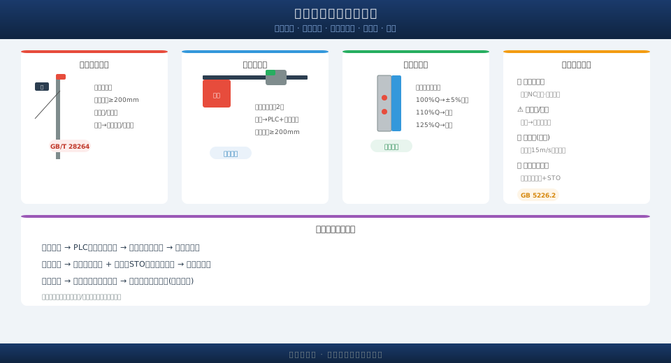
The lifting height limit switch is the most critical safety device preventing the hook from striking the upper structure. Per GB/T 28264, the clearance between the highest point of the lifting spreader and the upper limit switch must be no less than 200 mm. The commissioning procedure is as follows: 1) Manually jog the hoist in the up direction until the hook approaches the upper extreme position, and verify the trigger point of the upper limit switch; 2) Adjust the actuator arm of the limit switch or the sensing gap of the proximity switch so that the trip point corresponds to the spreader's highest position with a 200 mm safety margin; 3) After the limit is triggered, confirm that the hoisting mechanism is immediately de-energized for upward motion (while the lowering direction remains powered); 4) Repeat the trigger test three times to verify consistent operation. Heavy hammer limit switches and cam-type limit switches each have their own characteristics: the heavy hammer type is simple in construction but prone to nuisance trips, while the cam type offers higher accuracy but requires more complex adjustment. For VFD-controlled cranes with multi-speed hoisting, a deceleration limit switch (or an encoder-based threshold for pre-slowing) should also be configured.
| Safety device | Commissioning Standard | Trip value | Protective operation | Cycle |
|---|---|---|---|---|
| Hoisting Height Limiter | Lifting spreader Upper limit distance≥200mm | Trip travel | Hoist-up power cutoff/Lowering Hold | Quarterly |
| Travel Limit Switch | Trolley Wheel Base Rail end≥200mm | Buffer stop actuation | Traverse direction power cutoff | Quarterly |
| Overload Limiter | ±5%Accuracy | 110%/125%Q | Alarm/power-off shutdown | Annually |
| Emergency Stop Button | Forced contact separation≥3mm | Push-to-actuate | main contactor+STODisconnect | Daily |
Trolley and Crane Bridge Travel Limit Switch Adjustment
Travel limit switches on the crane bridge and trolley prevent the crane from running off the ends of the crane rail. The adjustment procedure is as follows: 1) Install limit stops at both ends of the rail (welded to the top of the rail); 2) Run the bridge or trolley at low speed (5Hz) toward the stops, and verify the stopping position when the limit switch is triggered; 3) Adjust the position of the stops or the limit switch mounting bracket so that the distance from the outer edge of the wheel to the rail end is ≥200mm after stopping; 4) After the limit switch is triggered, verify that travel in the opposite direction remains functional. Two independent limit switches (redundant) should be installed at each end of the bridge travel, with one wired to the PLC and the other directly cutting power to the main contactor (hardwired protection).
Overload Limiter Calibration Procedure
Calibration of the overload limiter (load limiter) is one of the most critical safety checks during installation and commissioning. Kelude uses a three-step calibration method with standard test weights to ensure accuracy in compliance with GB/T 28264 Safety Monitoring and Management System. Calibration is performed using standard test weights or a calibrated hydraulic load cell. The three-step verification process is as follows: 1) Rated load (100% Q) — the displayed value must be within ±5% of the actual load; 2) 110% Q — the audible and visual alarm must activate (the setpoint can be adjusted between 105% and 110%); 3) 125% Q — the power-off shutdown output must activate (cutting power to the hoisting/lifting motion while maintaining the lowering function). After calibration is complete, affix a calibration label to the instrument control panel indicating the calibration date, validity period, and the responsible person. The overload limiter must be sent to a certified metrology institution for verification once a year.
For load limiters using pin-type sensors, the sensor must be oriented so that the load application direction aligns with the sensor's sensitive axis. The sensor cable should be protected with a metal hose and routed separately, maintaining a minimum distance of 300mm from power cables to minimize electromagnetic interference.
Safety Device Integration and Interlock Testing
In addition to limit switches and the overload limiter, the following safety devices must be verified individually during commissioning: 1) Door interlock switches — the crane must not be able to start or travel when any access door or trolley inspection door is open (the main contactor control circuit is cut off); 2) Rail clamps / anchor devices — the clamping signal must be interlocked with bridge and trolley travel (the bridge must not travel while clamped); 3) Anemometer — for outdoor cranes, the crane must automatically stop and sound an alarm when wind speed exceeds the preset value (typically 15m/s); 4) Emergency stop buttons — pressing any emergency stop button on the operating stations or control panel must immediately de-energize the main contactor and apply the brakes. The logic of all safety devices must comply with the design drawings and the control system functional specification.
