

Crane Load Monitoring System Guide: Sensor Selection & Installation
Crane weighing systems rely on five core sensor types—pin-type, compression, S-type tension, plate-ring, and hydraulic—paired with digital indicators for real-time load measurement and overload protection. Accuracy spans C3 to C6 grades (combined error ±0.02%FS to ±1%FS), making these systems essential for safety supervision and trade settlement applications.
In modern lifting appliances, the weighing system has evolved from a simple overload protection device into a core safety subsystem that integrates real-time measurement, data logging, and remote monitoring. Under the Crane Safety Technical Supervision Regulation (TSG 51-2023), overhead and gantry cranes with a rated lifting capacity above 3t must be equipped with a load limiter. For trade settlement or process weighing applications, the system must also meet the accuracy classes defined by OIML R60. This article provides a systematic review of sensor selection, installation practices, calibration procedures, and common fault diagnosis for all five sensor types, offering a complete technical reference for design engineers and maintenance personnel.
The design calculations in this guide follow the core requirements of ISO 4301 Crane Design Standard and TSG 51 Safety Technical Specification for Special Equipment, with additional considerations for the specific accuracy demands of weighing applications. In engineering practice, sensor selection must also account for the hoisting mechanism configuration, wire rope pulley ratio, and load impact characteristics.
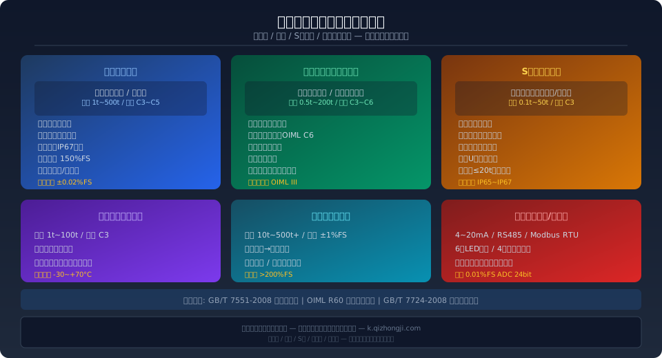
Weighing System Types and Operating Principles
A crane weighing system comprises four main components: sensors, signal transmitters, display indicators, and communication interfaces. The sensor converts the mechanical load into an electrical signal (mV-level voltage or 4–20mA current), which is amplified and filtered by the transmitter before being fed into the indicator for A/D conversion and digital processing. The final weight is displayed on a 6-digit LED or LCD screen. The system operates on the principle of resistance strain—when the elastic element deforms under load, the resistance of the bonded strain gauges changes, producing a differential voltage signal proportional to the load through a Wheatstone bridge circuit.
Based on mounting position and operating mode, crane weighing systems fall into two categories: direct measurement and indirect measurement. Direct measurement sensors (compression and pin-type) bear all or most of the suspended load directly, achieving accuracy up to OIML C6—suitable for trade settlement applications. Indirect measurement sensors (S-type tension and plate-ring) infer the load by measuring wire rope tension; they offer slightly lower accuracy but require minimal installation modification, making them ideal for retrofitting older equipment. Hydraulic weighing devices derive the load from cylinder pressure, offering the strongest impact resistance, though resolution is more susceptible to oil temperature variations.
Load Cell Selection and Accuracy Classes
Load cell accuracy is classified into six grades (C1 through C6) per OIML R60, with higher numbers indicating greater precision. C3 (combined error ≤±0.02%FS, verification interval n=3000) is the standard grade for industrial weighing; C4–C5 (n=4000–5000) serve higher-precision applications; and C6 (n=6000) meets trade settlement requirements. When selecting a sensor, the rated capacity should be 1.2 to 1.5 times the maximum actual load to provide margin for impact and fatigue. The sensor should also operate within 20% to 80% of its rated capacity to avoid nonlinearity errors near zero and full scale.
Pin-type sensors directly replace the pulley shaft or drum shaft, covering a measuring range from 1t to 500t. They require no additional space and are maintenance-free (IP67 protection rating), making them the most common choice for overhead and gantry cranes. Compression (spoke-type) sensors mount beneath the trolley frame or fixed pulley support, achieving the highest accuracy at C6—ideal for metallurgical overhead cranes requiring precise measurement, though they demand a machined mounting base. S-type tension sensors are installed in series at the dead end of the wire rope, requiring the least installation modification; they are the preferred option for electric hoists and small-capacity (≤20t) cranes. Plate-ring sensors mount at the equalizer sheave, offering strong resistance to vibration and off-center loading—particularly well suited for harsh metallurgical and foundry workshop environments.
Load Cell Technical Parameters: 5 Types Compared
The following side-by-side comparison evaluates five types of weighing sensors across accuracy, measuring range, mounting method, applicable working conditions, and cost — giving design engineers a quick reference for initial load cell selection.
| Sensor Type | Measuring Range | Accuracy Grade | Mounting Position | Applicationcrane | Cost Reference |
|---|---|---|---|---|---|
| Axle Pin Type | 1t~500t | C3~C5 (±0.02%) | pulley shaft/drum shaft | Overhead, Gantry, Metallurgical | Medium |
| Compression(Spoke Type) | 0.5t~200t | C3~C6 (±0.015%) | Trolley Frame/Fixed Pulley Under Base | Metallurgicaloverhead crane, Casting | Higher |
| STension Type | 0.1t~50t | C3 (±0.02%) | Wire Rope Fixing End/Hook block | Electric Hoist, Small Capacity | Low |
| Plate Ring Type | 1t~100t | C3 (±0.02%) | Equalizer Sheave Location | Metallurgical, Casting | Medium |
| Hydraulic Type 10t~500t+ | ±1%FS | Cylinder Pressure Port | ultra-large tonnage, Metallurgical | Higher |
Installation Specifications & Shaft Alignment Requirements
The accuracy and service life of a weighing system are directly determined by the quality of its installation. When mounting pin-type sensors, the pin-hole fit clearance must be held within the H7/g6 tolerance band—excessive clearance introduces additional bending moment errors. Apply a uniform coat of molybdenum disulfide grease to the pin shaft surface to prevent signal drift caused by fretting wear. For compression-type sensors, the mounting base flatness must not exceed 0.05 mm/m. Tighten the four mounting bolts in a diagonal sequence across three passes to the specified torque (typically 120–150 N·m for M16 bolts). After tightening, the sensor zero-point drift must remain within ±0.1 mV/V.
For S-type tension sensors, the axis of the connecting clevis and the wire rope must be strictly aligned, with a misalignment angle no greater than ±3°. Otherwise, side forces will increase the sensor's non-linearity error by 5–10%. All sensor signal cables must be twisted shielded pairs (shield grounded at a single point at the indicator end). Minimum separation distances from power cables: ≥200 mm when the power cable current is ≤50 A, ≥500 mm for 50–200 A, and ≥1000 mm for currents above 200 A. Signal cables must not be routed in the same conduit or tray as VFD output cables, as high-frequency PWM harmonics can cause erratic reading fluctuations.
Calibration at the indicator involves two steps: zero calibration and span calibration. For zero calibration, lower the hook to its lowest position with no load and press the "Zero" key so the display reads 0. For span calibration, lift a Standard Weight (at least 50% of rated load; 80%–100% is recommended) and hold it steady 10 seconds off the ground, then enter the actual weight of the test weight to complete calibration. After calibration, verify accuracy at four load points—20%, 50%, 80%, and 100%—ensuring the error at each point meets the hysteresis requirements of the corresponding accuracy grade.
Common Fault Diagnosis & Maintenance Guide
Weighing systems operating in harsh crane environments are subjected to vibration, oil contamination, and electromagnetic interference. Below are troubleshooting procedures and corrective actions for six common fault conditions, organized by symptom.
| Fault Symptom | Possible Cause | Troubleshooting Method | Resolution |
|---|---|---|---|
| Display Drift | Sensor Insulation Loweringor Junction box Water Ingress | Application500VMegohmmeter (Insulation Tester)Measure Sensor Insulation≥500MΩ | Bake Out Junction box, Replace Seal ring, Potting Silicone |
| Reading Fluctuation/Unstable | Electromagnetic Interference or Grounding Poor | oscilloscope Measure Signal Ripple, Compare with Shutdown/Running State | signal cable Add Ferrite Core, Single-Point Shield Grounding |
| High Zero Offset at No Load | Sensoroverload Plastic Deformation | Check Zero Output>1mV/V | Replace Sensor, Inspect Load Check if Exceeds150%FS |
| Poor Linearity, Large Point Errors | Sensor Elasticity Residual Stress or Eccentric Load | Step Load Test Output, Plot Linearity Curve | Re-calibrate and adjust installation alignmentaft alignment, Replace if Necessary Sensor |
| Indicator Display"OL"/"Err" | Sensor Open Circuit or Cable Damaged | multimeter Measure Bridge Circuit Resistance350Ω/700Ω | Segment by Segment Detection Cable Continuity, Replace Damaged Section |
| Error Increases with Temperature Change | Temperature Compensation Failureor Strain Gauge Aging | Temperature Test in Chamber for Zero and Sensitivity Coefficient | Replace Sensoror Upgrade Digital with Temperature Compensation Sensor |
Calibration, Verification, and Maintenance Intervals
In accordance with GB/T 7551-2008 (equivalent to OIML R60) for load cells, crane weighing systems used for trade settlement must undergo mandatory legal verification at intervals not exceeding 12 months. For systems dedicated to safety monitoring (overload protection), a functional check and simulated load test are recommended every 6 months. Daily maintenance follows a three-tier inspection schedule: per shift (8h), verify tnspection schedule: per shift (8h), verify the indicator returns to zero and the junction box seal is intact; weekly, inspect sensor cables for damage and check mounting bolts for looseness; monthly, perform a full-scale simulated load test, record output values at each load point, and compare with previous data—recalibration is required if the deviation exceeds ±0.1%FS.
The fatigue life of the sensor's elastic element is the primary factor determining its service life. Under normal operating conditions (load ≤80%FS, vibration acceleration ≤2g), foil strain-gauge sensors have a design life of approximately 10⁶ to 10⁷ load cycles. Based on 300 working days per year and 200 lifts per day, this translates to roughly 8–15 years of reliable service. However, under frequent full-load or impact-load conditions, residual stress accumulation in the elastic element accelerates zero drift. It is recommended that sensors be removed and sent to a metrology institute for full-parameter verification every 2–3 years. Digital sensors, with built-in temperature compensation and linearization algorithms, offer approximately 50% better long-term stability than analog sensors, making them ideal for applications requiring extended calibration-free operation.
Related Reading: Bridge Crane Load Limiter Calibration Procedure and Threshold Settings | Overload Limiter vs. Load Moment Limiter: Key Differences and Selection Guide | Understanding GB/T 12602-2020: Overload Protection Devices for Lifting Appliances
Frequently Asked Questions
Q: Which offers higher accuracy—pin-type or S-type load cells—and how do I choose?
A: Pin-type sensors achieve accuracy grades of C3–C5 (combined error ≤±0.02%FS), which is higher than the C3 grade (also ±0.02%FS) typical of S-type tension load cells. However, accuracy alone shouldn't drive the decision. Pin-type sensors replace the existing pivot pin and require precise machining for proper installation. S-type sensors, by contrast, can be integrated directly into the wire rope system using standard clevis mounts, cutting retrofit time by roughly 70%. For new installations or major overhauls of bridge and gantry cranes, pin-type sensors are the preferred choice. For retrofitting older electric hoists with weighing capability on a tighter budget, S-type sensors offer a more economical solution.
Q: The weighing readout is unstable and fluctuates. How can I tell if the sensor is faulty or if it's electromagnetic interference?
A: Use an oscilloscope to measure the sensor output signal under two conditions: motor stopped and motor running at full speed. If the signal is stable when stopped (ripple <5mVpp) but fluctuates significantly during operation, the cause is almost certainly PWM interference from the VFD. Check that the signal cable is separated from the power cable by at least 500mm and that the shield is grounded at a single point at the instrument end. If the signal is already erratic with the motor stopped, the issue is likely degraded bridge insulation in the sensor (measured as <200MΩ with a megohmmeter) or moisture ingress in the junction box. In this case, remove the sensor, dry it thoroughly, and replace the seals.
Q: How much does a crane weighing system cost? Does the price include installation and calibration?
A: A domestic pin-type weighing system (sensor + indicator + junction box) typically costs between $1,200 and $3,700 per set. Imported brands (HBM, FLINTEC, Vishay) range from $4,400 to $11,900 per set. An S-type tension sensor solution for electric hoists runs approximately $450 to $1,200 per set. On-site installation and calibration are usually quoted separately, ranging from $300 to $750 per installation depending on complexity. For systems used in trade settlement, an additional metrology institute verification fee of approximately $220 to $450 per test applies. Final pricing depends on the specific configuration outlined in the contract.
Q: Zero drift on my load cell has been getting worse over the years. Is it time to replace it?
A: The elastic element of a load cell accumulates residual stress and undergoes micro-plastic deformation under long-term cyclic loading, causing gradual zero and sensitivity drift. Per GB/T 7551-2008, a sensor should be replaced when annual zero drift exceeds ±2%FS or the sensitivity temperature coefficient exceeds ±0.05%FS/10K, even if it still produces a signal. For analog sensors in moderate crane duty (200 lifts/day, load ≤80%FS), the recommended replacement interval is 8–12 years. If a sensor has exceeded 100,000 load cycles and shows zero drift of ≥1mV/V, replacement is strongly advised.
Henan Kelude Heavy Industry Co., Ltd. provides complete crane weighing and metering solutions for bridge cranes, gantry cranes, metallurgical cranes, and explosion-proof models. We offer full selection and calibration support across pin-type, compression, S-type, plate-ring, and hydraulic sensor configurations. Visit k.qizhongji.com or call us for more information.
