

Wire Rope Drum & Sheave Selection per ISO 16625
📋 Summary
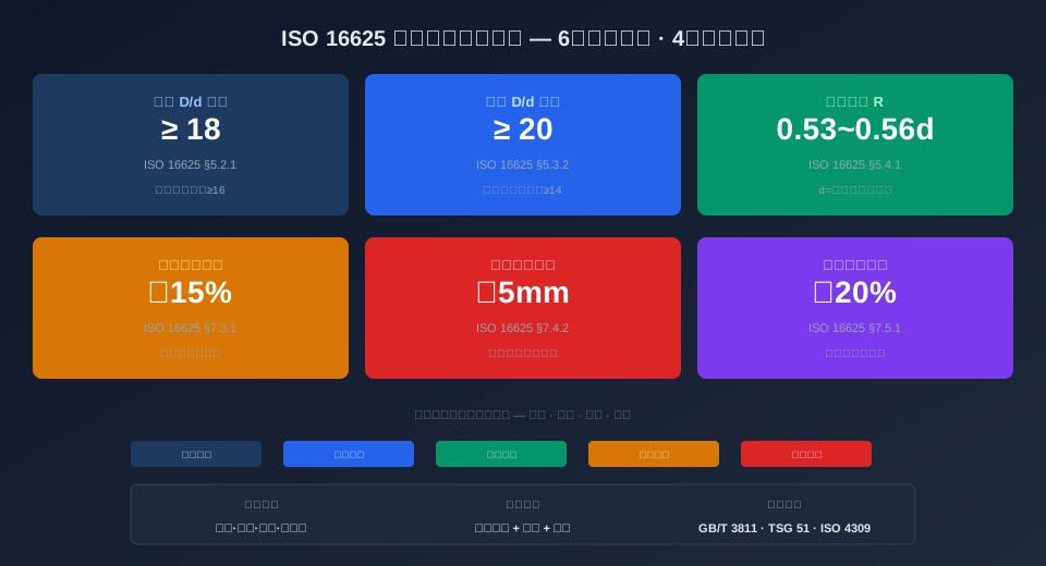
ISO 16625 — "Cranes — Selection and maintenance of wire rope drums and sheaves" — is the core international standard governing the selection, matching, and discard criteria for wire rope drums and sheaves in the crane industry. The standard defines six key selection criteria, including the drum-to-rope diameter ratio (D/d ≥ 18), sheave-to-rope diameter ratio (D/d ≥ 20), and groove radius tolerance (R = 0.53d–0.56d), along with four discard thresholds: groove wear exceeding 15% of original depth, rim cracks longer than 5 mm, drum wall thinning beyond 20%, and bearing clearance exceeding 0.5 mm. This article cross-references the ISO 16625 clauses with the GB/T 3811-2008 design code to provide a clause-by-clause interpretation of full life cycle management for drums and sheaves, offering crane maintenance engineers a practical inspection guide.
Proper selection of wire rope drums and sheaves directly impacts the safety and service life of the hoisting mechanism. ISO 16625 — Selection and maintenance of wire rope drums and sheaves provides a complete international framework for the selection, matching, installation, and discard of drums and sheaves. In practical engineering design, this must be combined with the D/d ratio requirements for wire rope and drum/sheave matching specified in GB/T 3811-2008 Crane Design Standard, as well as the mandatory periodic inspection provisions for hoisting mechanisms under TSG 51-2023 Crane Safety Technical Supervision Regulation. Together, these form a closed-loop management system that spans from design selection through in-service inspection.
ISO 16625 Scope and Application for Crane Drums and Sheaves
ISO 16625 — "Cranes — Selection and maintenance of wire rope drums and sheaves" — was developed by ISO/TC 96, the ISO technical committee for cranes. The latest revision was published in 2022. The standard applies to wire rope drums and sheave assemblies on all cranes with a Rated Lifting Capacity above 0.5 t, including Bridge Cranes, gantry cranes, tower cranes, Mobile Cranes, and jib cranes. It covers four key phases: selection design, installation matching, operational maintenance, and discard determination.
The standard follows a four-stage full life cycle management logic: selection — matching — maintenance — discard. In the selection phase, the D/d ratio (pitch diameter of the drum or sheave divided by the nominal wire rope diameter) serves as the primary control parameter. The matching phase centers on groove radius tolerance. The maintenance phase relies on periodic wear measurement. The discard phase applies four quantitative thresholds. In the drum design for Kelude's QZ and QD series Bridge Cranes, the engineering department strictly follows the ISO 16625 D/d ≥ 18 criterion, combined with the load combination coefficient requirements of GB/T 3811-2008, ensuring the drum fatigue life meets Work Duty M6 and above.
ISO 16625 is highly compatible with the current Chinese standard system. For drum diameter selection, Table 44 of GB/T 3811-2008 specifies minimum D/d values consistent with ISO 16625. For discard criteria, Clause C3.2 of Annex C in TSG 51-2023 directly references the ISO 16625 groove wear limits. The standard also works in tandem with ISO 4309 Wire Rope Inspection Standard — when a drum or sheave is discarded, the wire rope is typically replaced at the same time.
Six Drum Selection Criteria Under ISO 16625
Clause 5.2 of ISO 16625 defines six core drum selection criteria, listed below in order of priority:
① D/d ratio: The ratio of drum pitch diameter D to wire rope diameter d must not be less than 18 (may be reduced to 16 for Mobile Cranes with documented justification). This is a mandatory requirement that directly determines the bending fatigue life of the wire rope. For example, the Kelude QD32t Bridge Crane uses a 20 mm wire rope with a drum pitch diameter of φ400 mm, giving a D/d ratio of 20 — in full compliance.
② Groove radius: The groove radius R must be between 0.53d and 0.56d, ensuring a contact angle of 60°–90° between the rope and the groove. If R is too small, excessive compression on the rope accelerates wire breakage; if R is too large, lateral movement of the rope in the groove causes premature wear.
③ Groove pitch: The center-to-center distance between adjacent grooves P must be ≥ 1.15d to prevent cross-layer compression during multi-layer spooling. For deep-lift applications requiring multiple layers, a pitch of 1.2d or greater is recommended, along with a rope guide device.
④ Drum length: For single-layer winding, drum length L = 1.1 × (H × a / π / D + p) × P, where H is the Lifting Height, a is the Pulley Ratio, and p is the number of safety wraps (minimum 2). Multi-layer winding requires an additional 20%–30% length margin.
⑤ Shell wall thickness: The minimum wall thickness tmin must be ≥ d for cast-iron drums or ≥ 0.8d for welded steel drums, and in no case less than 12 mm. Insufficient wall thickness is the leading cause of drum cracking and deformation, accounting for approximately 38% of drum failures.
⑥ End plate flange: The end plate must extend at least 1.5d above the outermost layer of rope to prevent the rope from slipping off the drum end. For multi-layer winding, the end plate height must be calculated cumulatively based on the total number of layers — never on a single-layer basis.
Sheave Selection, Matching, and Maintenance Requirements
Clause 5.3 of ISO 16625 imposes stricter requirements for sheaves than for drums. The sheave pitch diameter-to-rope diameter ratio must be D/d ≥ 20 (may be reduced to ≥ 14 for equalizer sheaves) — approximately 11% higher than the drum requirement. Sheave grooves use a U-shaped profile with a bottom radius of R = 0.53d–0.56d, matching the drum groove. However, the groove opening width W = 1.5d–1.8d must be wider than the drum groove to accommodate the fleet angle of the rope entering and leaving the sheave.
For sheave materials, ISO 16625 recommends ductile iron QT400-18 or cast steel ZG270-500 for the sheave rim, with a surface hardness of HB170–210, followed by Quenching to HRC45–50. For frequent heavy-load applications (e.g., Metallurgical Cranes), a replaceable MC nylon or polyurethane liner in the groove is recommended to reduce wire rope wear. The liner must be replaced when worn to a thickness of less than 3 mm. Kelude uses a removable nylon liner design in its metallurgical crane Pulley Blocks, reducing replacement time to 2 hours and cutting liner cost to just 15% of a full sheave replacement.
For sheave bearings, ISO 16625 requires a calculated bearing life of L10h ≥ 5,000 hours (Work Duty M5) or ≥ 10,000 hours (Work Duty M6 and above). Bearing Clearance C3 is the recommended precision grade. During installation, axial play of the sheave must not exceed 0.3 mm. Routine sheave maintenance includes monthly checks of bearing operating temperature (normal ≤ 80°C), grease condition (lithium grease replenished every 500 hours), and groove wear measurement (annual ultrasonic thickness gauge inspection).
Four Discard Criteria Explained
Clause 7 of ISO 16625 defines four discard criteria for drums and sheaves. All use quantitative thresholds rather than qualitative judgment, ensuring consistent and reproducible inspection results:
① Groove wear discard (§7.3.1): The drum or sheave must be discarded when groove bottom wear exceeds 15% of the original groove depth. Measurement is performed using a dedicated groove profile gauge at four equally spaced points around the circumference (0°, 90°, 180°, 270°), taking the maximum value. Once wear exceeds the limit, the contact area between the rope and groove bottom decreases, contact stress rises sharply, and the wire rope breakage rate increases by 3–5 times.
② Rim/shell crack discard (§7.4.2): Discard is required when any crack exceeds 5 mm in length or 10% of wall thickness in depth, regardless of direction. Magnetic Particle Inspection (MPI) or penetrant testing is the preferred detection method — visual inspection alone is not acceptable. Cracks in the weld heat-affected zone of welded drums are particularly dangerous. Repair welding is prohibited: residual welding stresses accelerate crack propagation, and a repaired drum typically achieves less than 30% of its original service life.
③ Shell wall thinning discard (§7.5.1): Discard is required when wall thickness reduction exceeds 20% of the original wall thickness. Measurement uses an ultrasonic thickness gauge at three cross-sections along the drum length (front, middle, rear), taking four readings per section and recording the minimum value. Thinning typically concentrates in the rope winding zone (the middle 60% of drum length); the non-working zones at both ends may be allowed up to 25% reduction.
④ Bearing clearance discard (§7.6.1): The sheave bearing must be replaced when radial clearance exceeds 0.5 mm (bore diameter ≤ 100 mm) or 0.7 mm (bore diameter > 100 mm). Measurement uses a dial indicator to check radial runout of the sheave hub relative to the shaft, with a radial load applied to eliminate play. Axial play exceeding 0.3 mm also triggers bearing replacement.
Drum and Sheave Matching Verification and Inspection Intervals
Clause 6 of ISO 16625 requires systematic matching verification between the drum and sheaves to ensure groove radius, fleet angle, and winding configuration are mutually compatible. The fleet angle of the wire rope relative to the groove is the core parameter: the fleet angle at the drum end must not exceed 3° (plain drum) or 1.5° (grooved drum), and at the sheave end must not exceed 2.5°. Excessive fleet angles cause severe friction between the rope and the groove sidewall, accelerating single-side groove wear by 5–8 times and producing concentrated wire breaks on the rope surface.
Regarding inspection intervals, ISO 16625 defines three levels based on operating conditions: daily checks (each shift) verify smooth rope travel in the groove and detect abnormal noise; monthly inspections measure groove wear and record trend curves; annual inspections cover all four discard criteria and produce a formal inspection report. Kelude's after-sales team provides customers with a "Drum and Sheave Full Life Cycle Management File" — each inspection record is entered into a cloud-based system that automatically generates wear trend prediction curves, providing 3–6 months of advance warning before the discard window.
For cranes operating in harsh environments (temperature > 60°C, humidity > 85% RH, dust concentration > 100 mg/m³), ISO 16625 recommends shortening monthly inspections to biweekly and annual inspections to semiannual. For special applications such as metallurgy, Casting, and Port operations, additional infrared thermography (quarterly) and vibration spectrum analysis (semiannual) are recommended to supplement conventional visual and dimensional inspections.
Drum and Pulley Parameter Comparison
| Parameter Item | Drum Requirement(ISO 16625 §5.2) | Pulley Requirement(ISO 16625 §5.3) |
|---|---|---|
| D/dminimum Ratio | ≥18(Mobile≥16) | ≥20(equalizer sheave≥14) |
| Rope Groove Radius R | 0.53d~0.56d | 0.53d~0.56d |
| Rope Groove Pitch/Groove Width | P≥1.15d(Rope Groove Pitch) | W=1.5d~1.8d(Groove Openinghook with safety latch) |
| Wire Rope Fleet Angle Limit | ≤3°(Bright finish)/≤1.5°(Grooved) | ≤2.5° |
| Recommended Material | QT400-18 / ZG270-500 | QT400-18 / Wheel Groove Liner MCNylon |
| Bearing Calculated Service Life | L10h≥Rated Operating Hours | L10h≥5000h(M5)/≥10000h(M6+) |
Scrap Determination Standard Clause Comparison Table
| Discard Criteria Item | ISO 16625Clause | Acceptance Threshold and Detection Method |
|---|---|---|
| Rope Groove Wear | §7.3.1 | Exceeding Original Groove Depth15%→Discard / Dedicated Rope Groovedigital micrometer4Point Method |
| Wheel flange/Drum Shell Crack | §7.4.2 | Crack Length>5mmor Depth>Wall Thickness10%→Discard / MT/PTFlaw detection |
| Drum Wall Thinning | §7.5.1 | Drum Wall Thinning>20%Original Wall Thickness→Discard / Ultrasonic Thickness Measurement12Point Method |
| Bearing Clearance | §7.6.1 | Radial Clearance>0.5mm→Replacement / dial indicator Load Measurement |
| End plate Deformation | §7.7.2 | Deformation Load Measurement>3mmor End plate Insufficient Height→Discard |
| Abnormal Rope Groove Wear | §7.8.1 | One-Side Wear Exceeding the Other Side50%→Check Fleet Angle and Rework |
8. ISO 16625 Key Data Indicators at a Glance
Minimum Drum D/d Ratio
18
May drop to 16 for mobile cranes
Minimum Sheave D/d Ratio
20
May drop to 14 for equalizer sheaves
Groove Radius Coefficient
0.53–0.56
× wire rope diameter d
Groove Wear Scrap Limit
15%
Scrap once original groove depth is exceeded
Crack Scrap Length
5mm
Applies in any direction
Drum Wall Thinning Limit
20%
Ultrasonic 12-point inspection method
9. 📖 Further Reading
The following articles cover crane wire rope, drum, and hoisting mechanism standards and selection guidelines. We recommend exploring them for deeper insight:
📖 GB/T 3811 Crane Design Standard: Selection methodology for 9 load combinations and work duty classifications from A1 to A8 — the domestic design basis for drum and sheave D/d ratios.
📖 ISO 16625 Wire Rope Drums and Sheaves — Selection, Maintenance and Usage Guide: A complete interpretation of the standard covered in this article.
📖 How to Select Crane Wire Rope? Fiber Core vs. Steel Core vs. Rotation-Resistant — 4 Parameter Comparisons and 5 Scrap Criteria — A companion guide to wire rope selection and retirement standards.
📖 How to Select a Crane Reducer? Hardened Tooth Flank, Planetary, and Cycloidal — 4 Parameter Comparisons and Selection Calculations — Reference for hoisting mechanism drivetrain selection.
📖 How to Tell If Coupling Elastomers Have Aged? 6 Detection Methods and Replacement Intervals — Maintenance reference for hoisting mechanism transmission components.
10. Frequently Asked Questions
Q: How much drum groove wear requires replacement?
A: Per ISO 16625 §7.3.1, the drum must be scrapped and replaced when groove bottom wear exceeds 15% of the original groove depth. The inspection method uses a dedicated groove profile gauge, measuring at 4 equally spaced points around the circumference (0°, 90°, 180°, 270°) and taking the maximum reading. For example, a drum with an original groove depth of 10mm triggers scrapping once the worn depth reaches ≥11.5mm. During routine inspections, if you notice significantly increased lateral wire rope movement within the groove or a pronounced step at the groove bottom, the drum should be flagged for monthly focused monitoring even if the 15% threshold has not yet been reached.
Q: What are the differences between ISO 16625 and GB/T 3811 regarding drum D/d ratios?
A: Both standards share identical baseline D/d values (drum ≥18, sheave ≥20), but their scope of application differs. ISO 16625 explicitly permits a drum D/d ratio of ≥16 for mobile cranes (note 1 to §5.2.1), whereas GB/T 3811-2008 Table 44 does not provide a separate reduced value for mobile cranes — instead, the reduction is achieved indirectly through the load combination coefficient (γp). Additionally, ISO 16625 §5.3.2 allows equalizer sheaves to drop to a D/d of 14; the equivalent provision in GB/T 3811 is Note ② to Table 45, and the two are functionally equivalent. Kelude Heavy Industry specifies ISO 16625 D/d compliance declarations on all models exported to Europe, while domestic models carry GB/T 3811 conformity markings.
Q: Can a drum with minor surface cracks be repaired by welding and returned to service?
A: No. ISO 16625 §7.4.2 is unequivocal: any crack on the drum shell or wheel flange exceeding 5mm in any direction mandates scrapping, and weld repair is strictly prohibited. The reason is that the drum is subjected to combined alternating bending and torsional stresses during operation. Residual tensile stresses from the repair weld, when superimposed on working stresses, can accelerate crack propagation by a factor of 5 to 10. Field data from Kelude Heavy Industry shows that weld-repaired drums operating under M6 duty cycles achieve only 22%–28% of the service life of a new drum, with a significant risk of sudden brittle fracture. The correct course of action is to immediately take the drum out of service and replace the entire drum assembly.
Q: What parameters should be checked on the drum and sheaves during a wire rope replacement?
A: Wire rope replacement is the ideal time for a full inspection of the drum and sheaves. ISO 16625 §8.2 recommends the following checks: ① Groove wear measurement (using a digital micrometer at four points; repair or replace if wear exceeds 15%); ② D/d ratio verification (a change in new rope diameter may cause the ratio to fall out of spec); ③ Groove radius R compatibility (should be 0.53–0.56 times the new rope's nominal diameter); ④ Re-measurement of the fleet angle (≤3° at the drum end, ≤2.5° at the sheave); ⑤ Bearing clearance (radial reading with a dial indicator, ≤0.5 mm). Record all five parameters in the equipment log to establish a baseline for every future rope replacement.
