

GB/T 30024 Crane Structure Verification: Limit State and Fatigue S-N Curves
📋 Summary: GB/T 30024-2013 "Cranes — Proof of Competence of Steel Structures," identical to ISO 20332:2008, defines a four-dimensional verification framework covering strength, stiffness, stability, and fatigue strength of crane metal structures based on the limit state method. The standard classifies verification into ultimate limit state (ULS) and serviceability limit state (SLS), introducing partial safety factors in place of the traditional allowable stress method. It applies to all crane service ratings, from M1 light duty to M8 extra-heavy duty. Fatigue strength verification is mandatory for structures rated M5 and above, using S-N curves across 14 construction detail categories (Z1–Z14). This article explains the value rules for six types of partial safety factors, walks through the five-step verification workflow, and demonstrates the complete process with a 100t casting crane main girder example.
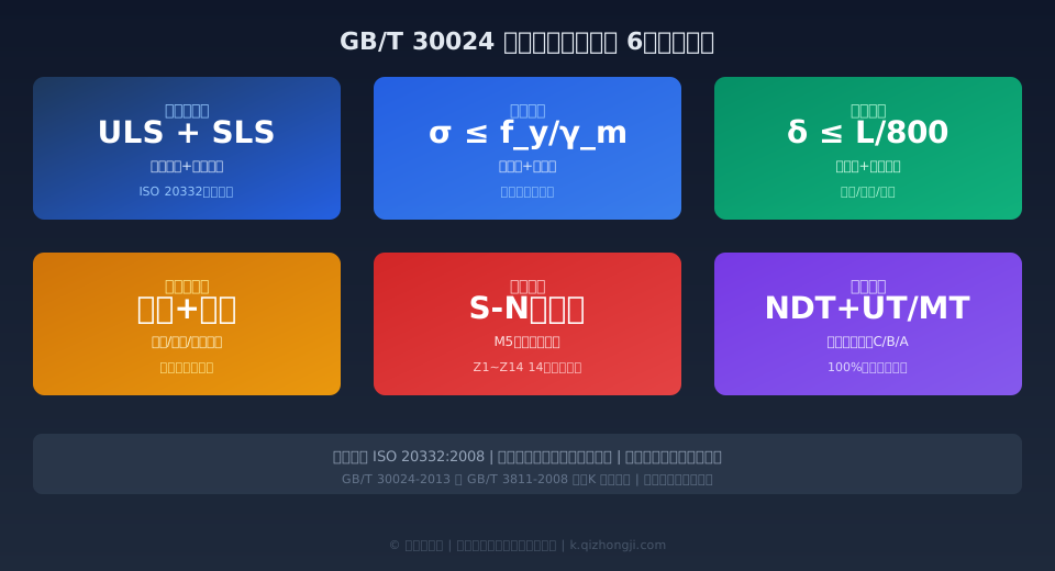
Standard Framework and Application Scope
GB/T 30024-2013 is the foundational standard for the design verification of crane steel structures. Identical to ISO 20332:2008, it applies to the load-bearing capacity verification of steel structures across all crane types. The core principle upgrades structural verification from the traditional single safety factor approach to the limit state method with partial safety factors, effectively refining and supplementing Annex K of GB/T 3811-2008.
The standard covers an extremely broad product range: bridge, gantry, tower, mobile, portal, railway, and floating cranes. Verification is broken down into four dimensions: strength (static strength plus elastoplastic behavior), stiffness (static deflection plus dynamic stiffness), stability (local buckling, global instability, and lateral-torsional buckling), and fatigue strength (mandatory for M5 and above).
It complements the test specification in GB/T 5905-2011 — the latter governs complete machine testing and acceptance, while GB/T 30024 focuses on design-stage calculation verification. Together they form a closed loop of "design verification + test validation." The standard also sets conditions for using finite element analysis (FEA) as a supplementary verification tool, requiring mesh sizes of 5–10 mm in critical stress concentration zones.
Limit State Method and Six Partial Safety Factors
The limit state method classifies structural failure into two categories. The ultimate limit state (ULS) corresponds to a structure or component reaching its maximum load-bearing capacity, buckling, or fatigue failure — involving personnel safety and major equipment loss, and carrying the highest safety level. The serviceability limit state (SLS) corresponds to deformation, vibration, or localized damage that affects normal operation, with a lower safety level.
The partial safety factor system is the core tool of the limit state method, comprising six factors that fine-tune loads and resistances:
① Load partial safety factor γp: 1.05–1.20 for dead loads, 1.10–1.50 for lifting loads (upper bound for M8 duty);
② Dynamic coefficients φi: hoisting impact allowance φ1 (1.0–1.1), hoisting dynamic load factor φ2 (1.15–2.0, dependent on lifting speed), and sudden load release factor φ3 (1.0–1.5);
③ Combination factor ψ: reduction factor accounting for the probability of simultaneous loading — ψ = 0.9 for travel mechanism combined with hoisting mechanism, ψ = 0.8 for wind load combined with working load;
④ Resistance partial safety factor γm: 1.05–1.10 for steel strength, 1.15–1.25 for weld seams, 1.15–1.25 for bolted connections;
⑤ Importance factor γn: three levels based on failure consequences (γn = 0.9/1.0/1.1), with 1.1 applied to hoisting mechanisms involving personnel safety;
⑥ Fatigue load partial safety factor γf: typically 1.0–1.1, based on measured load spectrum data or empirical values.
Five-Step Verification Workflow and Weld Detail Checks
GB/T 30024 specifies a five-step verification procedure for steel structures. Step one — determine load cases and load combinations: select the most unfavorable conditions from the load combination tables in Annex A, based on the crane service rating and actual operating scenarios. At minimum, three combinations must be considered: working without wind, working with wind, and special loads. Step two — calculate internal forces and stresses: use elastic analysis to determine bending moments, shear forces, axial forces, and torque in sections, accounting for second-order (P-Δ) effects on slender compression members.
Step three — strength verification: compute equivalent stress using the von Mises yield criterion, σeq = √(σ² + 3τ²), and compare against the design strength fd = fy/γm, requiring σeq ≤ fd. For offset rail box girder webs subjected to significant shear stress, the equivalent stress typically runs 30%–50% higher than the uniaxial normal stress, making these the most severe stress concentration zones in the structure.
Step four — stiffness and stability verification: main girder static deflection limits are δs ≤ L/800 for general bridge cranes and δs ≤ L/1000 for precision hoisting cranes; tower crane mast top horizontal displacement is limited to H/100. Local stability is checked against width-to-thickness ratio limits for plates — when the web height-to-thickness ratio h0/tw exceeds the limit, transverse stiffeners must be provided at spacing a ≤ 2h0. Global stability is verified against the critical moment for lateral-torsional buckling; for doubly symmetric box section main girders, lateral-torsional buckling typically does not govern the design due to the high torsional stiffness of the box section.
Step five — weld detail verification: weld quality grades are classified as C (standard), B (medium), and A (high). Butt welds in tension require 100% Ultrasonic Testing (UT), while fillet welds require 20% Magnetic Particle Inspection (MPI). In fatigue-sensitive zones, weld surface roughness must be Ra ≤ 6.3 μm and weld reinforcement ≤ 1.5 mm. Critical joints — main girder-to-end carriage connections and trolley rail joints — require a weld quality grade of at least B.
Fatigue Strength Verification and S-N Curves
Fatigue strength verification is mandatory for crane designs rated M5 and above. Per Annex B of GB/T 30024, welded joints are classified into 14 fatigue detail categories, Z1 through Z14, each with a corresponding S-N curve characterized by the fatigue strength Δσc at N = 2×10⁶ cycles. Z1 (polished parent metal, no welding) has the highest rating at Δσc = 160 MPa, while Z14 (welded lattice column joints) is the lowest at Δσc = 32 MPa.
The fatigue verification procedure follows three steps: determine the design life and number of cycles (A5 typically Nd = 2×10⁶–4×10⁶ cycles; A7 Nd = 6×10⁶–1×10⁷ cycles) → use the load spectrum factor Kp to convert variable-amplitude stress to an equivalent constant-amplitude stress, Δσeq = Kp^(1/m) × Δσmax (m = 3 for welded structures) → calculate the permissible stress range [Δσ] = (Δσc^m × 2×10⁶/Nd)^(1/m) and verify that γf × Δσeq ≤ [Δσ]/γm.
Using a Kelude A7 100t ladle crane main girder as an example: mid-span bottom flange butt weld (Z4 category, Δσc = 112 MPa), design life Nd = 8×10⁶ cycles, measured stress range Δσeq = 58 MPa. Permissible stress range [Δσ] = (112³ × 2×10⁶ / 8×10⁶)^(1/3) = 70.6 MPa. Check: 1.05 × 58 = 60.9 MPa > 70.6/1.25 = 56.5 MPa — not satisfied. Kelude applied a weld grinding solution to upgrade the detail from Z4 to Z3 (Δσc = 125 MPa, [Δσ] = 78.9 MPa), combined with 100% UT inspection to reduce γm to 1.15, ultimately passing the verification.
Fatigue improvement options include weld grinding (upgrade of one detail category), TIG remelting (20%–30% life improvement), ultrasonic impact treatment (UIT) (50%–100% life improvement), and weld end radius transition R ≥ 25 mm (Z6→Z5, a 27% improvement). Kelude prioritizes UIT treatment for critical fatigue-prone joints.
FEA-Assisted Verification and Worked Example Comparison
GB/T 30024 explicitly permits finite element analysis (FEA) as a supplementary verification tool alongside analytical calculations, provided the FEA model is calibrated against test data or established case studies. Shell elements (Shell181/Shell281) are recommended for plate and shell structures, with a global mesh size of 20–50 mm refined to 5–10 mm in stress concentration zones. Boundary conditions must accurately model bogie support constraints (simply supported or elastic supports), and loads are applied in load steps matching actual operating conditions.
FEA acceptance criteria: static strength analysis requires von Mises stress ≤ allowable material stress, with linearized membrane plus bending stresses meeting the limits for each stress classification (per the ASME VIII-2 stress classification method). Buckling analysis requires a first-order linear buckling eigenvalue ≥ 3.0 (≥ 2.0 after reduction for initial imperfections), while nonlinear buckling analysis considers initial imperfection amplitudes of L/1000 to L/500.
For a 100t metallurgical crane project, Kelude built an integrated main girder plus end carriage FEA model in ANSYS Workbench, using approximately 120,000 shell elements and solving six load cases. FEA results deviated from GB/T 30024 analytical calculations by less than 8% — mid-span maximum deflection was 12.3 mm from FEA versus 11.8 mm analytically (a 4.1% deviation), confirming the conservative and reliable nature of the standard's analytical formulas. The FEA identified a stress concentration factor of 2.3 at critical welded joints, higher than the 1.8 estimated analytically, prompting an upgrade of the weld grade in those areas.
The standard also requires all calculation reports and FEA documentation to be archived for at least 10 years, serving as baseline data for periodic inspection and life extension assessments. Kelude maintains a "structural digital archive" for every crane rated A5 and above, containing the initial design calculation report, FEA model files, factory test data, and annual camber measurement records.rchive" for every crane rated A5 and above, containing the original design calculations, FEA model files, factory test data, and annual camber measurement records.
Kelude Double-Girder Overhead Crane
Kelude double-girder overhead cranes are engineered for heavy-duty material handling in industrial workshops, warehouses, and production lines. Built for demanding environments, these cranes deliver reliable lifting performance with precise control and long-term durability.
Frequently Asked Questions
Q: What is the maximum span available for a double-girder crane?
A: The standard maximum span is 34.5 meters, but larger spans can be engineered upon request depending on the site conditions and load requirements.
Q: Can the crane be used outdoors?
A: Yes, with appropriate weatherproofing and protective coatings, our double-girder cranes are suitable for outdoor service in various climatic conditions.
Q: What is the typical lead time for a custom crane?
A: Standard models typically ship within 30-45 days. Custom-engineered solutions may require 8-12 weeks depending on complexity.
| partial factor Coefficient | symbol | value Specification |
|---|---|---|
| Loadpartial factor Coefficient | γ_p | dead load1.05~1.20, Hoisting / Lifting1.10~1.50 |
| dynamic Coefficient | φ_i | φ_2=1.15~2.0(according to Lifting Speed) |
| combination Coefficient | ψ | multiple Load combination0.8~0.9 |
| resistance partial factor Coefficient | γ_m | Steel1.05, Weld Seam1.15~1.25 |
| importance Coefficient | γ_n | 0.9/1.0/1.1(Class III) |
| Fatiguepartial factor Coefficient | γ_f | 1.0~1.1(according to Load spectrum) |
| construction details Grade | Δσ_c(MPa) | typical application location |
|---|---|---|
| Z1(parent metal grinding) | 160 | non-Weldingparent metal zone |
| Z4(Butt Weld) | 112 | Main Girderflange butt joint |
| Z6(Stiffener / Stiffening Ribend) | 90 | transverse Stiffener / Stiffening Rib Weld Seamend |
| Z8(incomplete penetration cross) | 71 | Diaphragmand Web plateconnection |
| Z11(friction-type Bolt) | 50 | End Carriage Flange Connection |
| Z14(lattice column joint) | 32 | truss tower joint |
6-Point Verification Data at a Glance
A: Limit State Method
ULS+SLS
Load-bearing + Serviceability
Strength Acceptance Criterion
σ_eq≤f_y/γ_m
von Mises equivalent stress
Main Girder Deflection Limit
L/800~L/1000
General / Precision hoisting
Buckling Eigenvalue Limit
λ_cr≥3.0
First-order linear buckling
Fatigue Classification Range
Z1~Z14
160→32MPa decreasing
Weld Quality Grades
C/B/A Grades
UT/MT inspection ratio
Further Reading
📖 GB/T 3811 Crane Design Standard: Load Combination Selection for Work Duty Classes A1 to A8 — The governing design standard and theoretical basis for the fatigue verification covered in this article.
📖 GB/T 5905 Crane Test Specification: 3 Load Test Procedures and 6 Acceptance Criteria — Closing the verification loop through practical testing of design calculations.
📖 GB/T 30220 Crane Brake Standard: 8 Performance Indicators and a 5-Step Selection Method — Safety component selection that complements structural design.
📖 GB/T 32071 Buffer Standard Explained: 6 Selection Parameters, 4 Test Methods, and 3-Level Energy Calculation — End-stopping buffers and their role in structural protection.
FAQ
Q: What is the difference between GB/T 30024 and Annex K of GB/T 3811 in fatigue verification?
A: Annex K of GB/T 3811 provides S-N curves and construction detail classifications (Z1–Z14), forming the foundational framework for fatigue verification. GB/T 30024 builds on this by introducing partial safety factors (γ_m = 1.15–1.35 and γ_f = 1.0–1.1) and defining operational procedures for finite element-assisted verification. The two standards work together: first select the construction detail class and allowable stress amplitude per GB/T 3811, then complete the verification calculation using the partial safety factor method of GB/T 30024.
Q: What specific requirements does GB/T 30024 impose on weld flaw detection ratios?
A: The standard classifies weld quality into three grades — C, B, and A. Butt welds under tension require 100% Ultrasonic Testing (UT per GB/T 11345), while fillet welds require 20% Magnetic Particle Inspection (MT per JB/T 6061). For fatigue-sensitive zones (welded joints with stress amplitude ≥ 50 MPa), the weld surface roughness must meet Ra ≤ 6.3 μm with reinforcement height ≤ 1.5 mm. Grade A welds additionally require Radiographic Testing (RT) with a sampling rate of no less than 10%. Critical joints — such as main girder-to-end carriage connections and trolley rail joints — must achieve at least Grade B weld quality.
Q: How much do the load partial safety factors γ_p differ between duty classes M5 and M8?
A: Load partial safety factors increase with duty classification. For dead loads: γ_p = 1.05 (classes M1–M4) → 1.10 (classes M5–M6) → 1.20 (classes M7–M8). For lifting loads: γ_p = 1.10 (classes M1–M3) → 1.25 (classes M4–M5) → 1.35 (classes M6–M7) → 1.50 (class M8). Comparing class M8 with class M5, the lifting load partial factor rises from 1.25 to 1.50 (a 20% increase). Combined with the difference in dynamic coefficient φ_2 (class M8 takes the upper limit of 2.0 versus 1.3 for class M5), the design load for class M8 is approximately 1.8–2.3 times that of class M5.
Q: How should main girder deflection exceeding the L/800 standard limit be addressed?
A: When main girder deflection exceeds L/800 (general-purpose bridge cranes) or L/1000 (precision hoisting applications), an immediate structural assessment is required. Per the SLS verification in ISO 4301, if the deflection is elastic and the girder recovers well after a static load test (permanent deformation ≤ S/2000), the crane may be derated for continued service. If camber loss exceeds 30% of the original value, Kelude recommends either a prestressing method (welding a tension plate to the lower flange at mid-span) or a stiffness reinforcement approach (welding longitudinal stiffeners to both sides of the web plate) to restore the girder. Cranes rated A7/A8 should trigger an evaluation at 20% camber loss to avoid reaching the point where a full girder replacement becomes necessary. All repair solutions must pass strength and fatigue verification in accordance with ISO 4301.
