

GB/T 10183 Crane Rail Tolerances: 5 Key Metrics Guide
GB/T 10183-2018, "Tolerances for Manufacture and Rail Installation of Bridge and Gantry Cranes," is the core standard governing wheel and rail installation accuracy for cranes. It is identical to ISO 12488-1:2012. This standard defines five key technical indicators—span tolerance S, track gauge tolerance K, wheel skew, rail straightness, and diagonal deviation—along with their measurement methods. It applies to the entire lifecycle of bridge, gantry, and semi-gantry cranes with lifting capacities from 1t to 500t, covering manufacturing, installation, commissioning, testing, and acceptance inspection.
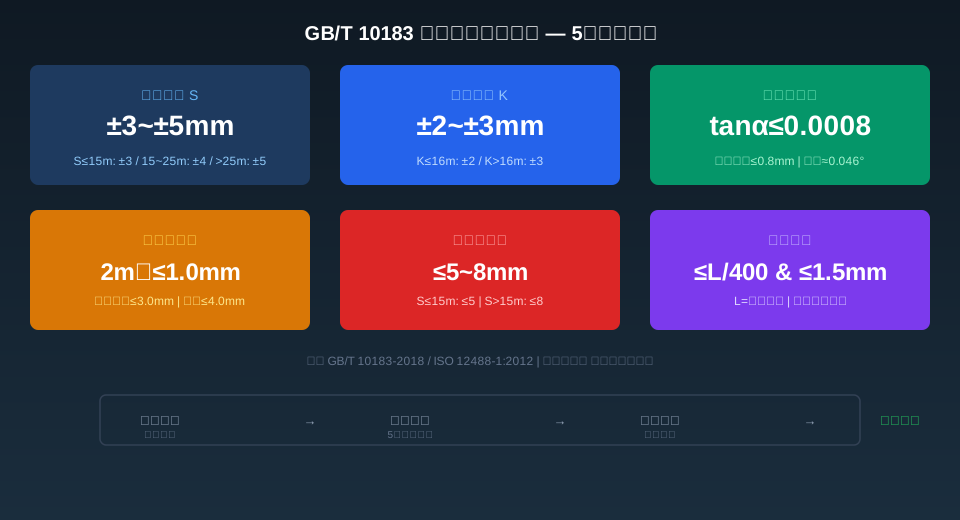
GB/T 10183 Scope and 5 Key Tolerance Indicators
GB/T 10183-2018, officially titled "Tolerances for Manufacture and Rail Installation of Bridge and Gantry Cranes," is administered by the National Technical Committee on Cranes (SAC/TC 227) and was published and implemented in December 2018. The standard is identical to ISO 12488-1:2012, fully aligning with international practice, and serves as the benchmark document for Kelude Heavy Industry's rail installation operations.
The standard applies to the manufacturing tolerances of wheel assemblies and the installation tolerances of bridge runway rails for bridge cranes, gantry cranes, and semi-gantry cranes. It covers precision control across the full lifecycle, from the manufacturing workshop to on-site installation. Five key indicators are controlled:
① Span tolerance S — allowable deviation in the span of the crane bridge runway rails; directly affects the alignment of the crane bridge during travel.
② Track gauge tolerance K — deviation in the centerline spacing between the two rails on the same side; determines the clearance between the wheels and the rails.
③ Wheel skew — horizontal skew angle of the wheel tread relative to the rail centerline; a critical parameter for preventing wheel-rail gnawing (flange rubbing).
④ Rail straightness — straightness deviation of the rail top surface in both horizontal and vertical directions; affects travel smoothness.
⑤ Diagonal deviation — difference in length between the two diagonals of the rectangular bridge runway rail frame; verifies overall squareness of the rail layout.
These five indicators work in conjunction with the provisions on steel structure stiffness and travel mechanism design in GB/T 3811-2008 "Crane Design Standard". The stiffness margin reserved during the design phase directly influences the tolerance compliance rate during installation. Kelude Heavy Industry pre-adjusts wheel assemblies to GB/T 10183 tolerances before the bridge crane leaves the factory, ensuring an on-site installation tolerance pass rate of ≥98%.
Span and Track Gauge Tolerances: First Line of Installation Accuracy Control
Span S refers to the span of the bridge runway rails—the horizontal distance between the centerlines of the two rails. GB/T 10183 divides tolerances into three tiers based on span: ±3mm for S≤15m, ±4mm for 15m<S≤25m, and ±5mm for S>25m. A total station or a calibrated steel tape measure is recommended for measurement, which must be performed at an ambient temperature of 20℃±5℃ to avoid systematic errors from thermal expansion or contraction.
Track gauge K is the horizontal distance between the centerlines of the crane bridge wheel treads. The standard specifies a tolerance of ±2mm for K≤16m and ±3mm for K>16m. In practice, Kelude Heavy Industry uses a laser distance sensor with a reflective target to take bidirectional measurements and averages the results, keeping single-side track gauge deviation within ±1.5mm—stricter than the national standard requirement.
It is worth noting that TSG 51-2023 "Safety Technical Specification for Special Equipment" (Article 7) explicitly requires a geometric dimension re-check after rail installation and before the load test. If span or track gauge deviations exceed the limits, the load test must not proceed. This regulatory requirement, combined with the tolerance limits in GB/T 10183, creates a dual quality assurance mechanism: standard specification plus mandatory supervision.
Wheel Skew and Vertical Deviation: The Foundation of Smooth Bridge Travel
Wheel skew is the core parameter affecting the smoothness of crane bridge travel and the leading cause of wheel-rail gnawing. GB/T 10183 defines wheel skew as the angle between the tangent of the wheel tread in the horizontal plane and the rail centerline. The standard specifies that the tangent of this skew angle must satisfy tanα≤0.0008, meaning no more than 0.8mm of skew per meter of wheel base.
The measurement method involves establishing a rail centerline reference using a theodolite or laser alignment instrument, then mounting a dial indicator on the wheel flange face and rotating the wheel 360° to read the radial runout. Three equally spaced points are measured on each wheel, and the maximum value is used as the skew determination. Kelude Heavy Industry pre-assembles and adjusts wheel blocks using a coordinate measuring machine at the factory stage, keeping skew within tanα≤0.0005—well above the national standard requirement.
Vertical deviation (vertical skew of the wheel) is equally important. The standard requires that the deviation of the wheel tread from the vertical plumb line in the vertical plane be ≤L/400 (where L is the wheel diameter), with an absolute value not exceeding 1.5mm. This indicator directly affects the contact stress distribution between the wheel and rail. Excessive deviation accelerates single-side flange wear and can shorten wheel service life by 30%–50%.
Rail Straightness and Diagonal Deviation: Tracing the Root Cause of Wheel-Rail Gnawing
Rail straightness is assessed in two dimensions: horizontal and vertical. Horizontal straightness refers to the straightness deviation of the rail top surface centerline in the horizontal plane. GB/T 10183 specifies a deviation of ≤1.0mm over any 2m section and ≤3.0mm over the full length. Vertical straightness, i.e., the elevation deviation of the rail top surface, must be ≤1.0mm over any 2m section and ≤4.0mm over the full length.
On-site inspection uses a φ0.5mm piano wire as a reference line with a steel rule for reading, or an electronic level instrument for surface scanning. Kelude Heavy Industry recommends a 48-hour static observation period immediately after rail installation to allow foundation settlement to stabilize before the final measurement. Height misalignment at rail joints must be kept within 0.5mm, with a joint gap of 3–5mm, and the rails must be securely fixed with rail clamps.
Diagonal deviation is a comprehensive indicator of the "squareness" of the rectangular rail frame. The standard specifies the absolute difference between the two diagonal lengths: ≤5mm when span S≤15m, and ≤8mm when S>15m. Excessive diagonal deviation means the rail frame forms a parallelogram rather than a rectangle, causing the wheels to run in a continuously skewed state relative to the rails—another major cause of severe wheel-rail gnawing.
3-Step Inspection and Acceptance Process: From Measurement Prep to Report Archiving
Step 1: Pre-measurement preparation and reference establishment. Clear debris and weld slag from the rail installation area, and mark measurement cross-sections every 2m along the full rail length with a marker pen. Use a total station to establish a coordinate system origin at one end of the rail, and set out two control lines along the rail centerline direction: the span reference line and the track gauge reference line. All measuring equipment (total station, steel tape, dial indicator, level instrument) must be calibrated and within its validity period, with an accuracy grade no lower than one-third of the standard requirement.
Step 2: Item-by-item measurement and data recording. Measure in the following order: span, track gauge, wheel skew, horizontal straightness, vertical straightness, and diagonal deviation. Record three readings at each cross-section and take the average to eliminate random errors. Span measurement must cover at least five cross-sections: both rail ends, quarter-span, mid-span, and three-quarter-span. Diagonal deviation is calculated using total station coordinate back-calculation, which is an order of magnitude more accurate than direct tape measurement.
Step 3: Deviation assessment and acceptance archiving. Compare the measured data against the tolerance limits specified in GB/T 10183 one by one. If any indicator exceeds the tolerance, the installation is deemed non-conforming and must be adjusted and re-measured. The acceptance record must include six items: measurement date, ambient temperature, surveyor signature, instrument serial number, raw data sheets, and a deviation summary table. These records are archived for the entire lifecycle of the crane. All rail installation acceptance records for Kelude Heavy Industry's factory-delivered products are incorporated into the ISO 9001 Quality Management System digital archive.
5 Tolerance Indicators and Measurement Methods Comparison Table
| Tolerance Indicator | Standardlimit value(GB/T 10183) | recommended measuring tool |
|---|---|---|
| Span Tolerance S | S≤15m:±3mm; 15~25m:±4mm; >25m:±5mm | total station/steel coilruler+tension meter |
| Track Gauge Tolerance K | K≤16m:±2mm; K>16m:±3mm | Laser Distance Sensor / Laser Rangefinder/caliper |
| wheel skewness | tanα≤0.0008(skewness per meter≤0.8mm) | theodolite+dial indicator/laser alignment device |
| vertical Deviation | ≤L/400and≤1.5mm | frame-type spirit level/electronicinclinometer |
| Crane Rail Straightness | 2minternal≤1.0mm; full length≤3.0mm/4.0mm | piano wire+Steel Plateruler/Level Instrument |
| diagonal Deviation | S≤15m:≤5mm; S>15m:≤8mm | total stationcoordinate inverse calculation/steel coilruler |
Crane Service Rating vs. Installation Tolerance Grade: A Practical Selection Guide
| Work Duty / Classification(A1~A8) | recommended Tolerance Grade | typical application scenarios and Kelude products |
|---|---|---|
| A1~A3(light duty) | Standardlight duty(GB/T 10183reference value) | maintenance bay crane/Assembly Line Hoist |
| A4~A5(medium duty) | precision class(reference value×0.7) | Machinerymachining Workshop/medium-frequency furnace charging |
| A6~A7(heavy duty) | high-precision class(reference value×0.5) | metallurgical crane/Castingmaintenance bay crane/steel coilhoisting |
| A8(extra heavy duty) | ultra-high-precision class(reference value×0.3) | nuclear powerpolar crane/shipyard Gantry Crane |
| offset rail/unequal rail heights | tightened class(Track Gauge Tolerance ±3mm±1.0mm) | offset rail box girder Gantry Crane/large Span Unloading Bridge |
| Explosion-proof/clean environment | special class(per special standard) | chemical plant Explosion-proofmaintenance bay crane/electroniccleanroommaintenance bay crane |
Key Tolerance Data at a Glance
Span S ≤ 15m
±3mm
Span tolerance limit
Track Gauge K ≤ 16m
±2mm
Track gauge tolerance limit
Wheel skew angle
0.046°
tanα ≤ 0.0008
Rail straightness / 2m
1.0mm
Horizontal & vertical
Diagonal difference ≤
5–8mm
Varies by span length
Vertical deviation ≤
1.5mm
Whichever is less: L/400
Related Reading
For more on crane installation and operational accuracy control, we recommend the following articles:
How to Calculate Crane Bridge Travel Resistance? Friction, Wind, and Slope Resistance Formulas with Drive Power Selection Chart — Rail installation tolerances directly affect travel resistance; tighter tolerances mean lower energy consumption.
How to Detect and Repair Trolley Frame Deformation on Overhead Cranes? 5 Measurement Methods and Flame Straightening Procedures — Trolley frame deformation and track accuracy are interdependent and must be controlled in tandem.
Single-Girder vs. Double-Girder Bridge Crane: How to Choose? 5–20t Capacity Comparison and 5 Decision Factors — Different girder types impose significantly different rail installation accuracy requirements, so this should be factored in at the selection stage.
Frequently Asked Questions
Q: What exactly is the difference between the GB/T 10183 and ISO 12488 rail tolerance standards?
A: GB/T 10183-2018 is an identical adoption of ISO 12488-1:2012, meaning the tolerance values are exactly the same with no technical differences. The main distinction lies in the document structure: ISO 12488 is split into Part 1 (bridge and gantry cranes) and Part 2 (mobile cranes), while GB/T 10183 covers only the bridge and gantry crane portion. Additionally, the Chinese standard adds Annex A, "Measurement Method Examples," which provides illustrated step-by-step procedures for using total stations and steel tape measures — making it more practical for field use. For export projects, Kelude directly references ISO 12488 as the acceptance criterion, while domestic projects in China follow GB/T 10183.
Q: What specific inspection requirements does GB/T 10183 set for wheel skew on overhead cranes?
A: Clause 6.3 of GB/T 10183 specifies a horizontal skew limit of tanα ≤ 0.0008, which equates to a maximum deviation of 0.8mm per meter of wheel base. The measurement procedure follows Annex A.3: mount a dial indicator against the wheel end face, rotate the wheel one full revolution to record radial runout, and take readings on both the outer and inner end faces. The skew value is calculated as half the difference between the two readings. Vertical skew, per Clause 6.4, must not exceed L/400 (where L is the wheel diameter) with an absolute limit of 1.5mm. Key precautions during inspection: ① eliminate bearing clearance in the wheel block; ② ensure the measuring surfaces are clean and free of oil; ③ maintain a stable ambient temperature within 20°C ± 5°C.
Q: How should I systematically troubleshoot rail installation tolerances when a crane exhibits severe wheel rail gnawing during operation?
A: Follow this step-by-step sequence for diagnosing flange rubbing: ① Measure the track gauge K — if the deviation between the two rails exceeds ±3mm, prioritize gauge adjustment; ② Stretch a piano wire to check horizontal straightness — any 2m segment exceeding 1.0mm indicates rail bending that requires correction; ③ Use a level instrument to measure vertical straightness (rail elevation) — deviations exceeding 4mm over the full length can cause wheels to lose contact; ④ Use a total station to measure diagonal differences — values beyond 5–8mm indicate an out-of-square rail frame; ⑤ Finally, check wheel skew — if the first four items all pass but wheel skew is out of tolerance, adjust the wheel block individually. Kelude's after-sales service team is equipped with laser runway survey detectors and can complete a full 6-indicator precision diagnosis of the entire rail system within 2 hours.
Q: What straightness tolerance is typically required for rail installation on a 5-ton overhead crane?
A: A 5-ton overhead crane typically has a span between 10m and 20m. Per GB/T 10183, horizontal straightness must be ≤1.0mm over any 2m test segment, and ≤3.0mm over the full rail length (assuming 16m). Vertical straightness is ≤1.0mm over a 2m segment and ≤4.0mm over the full length. In practice, Kelude tightens the full-length horizontal straightness target to 2.0mm and vertical straightness to 2.5mm—well above national standard requirements. At rail joints, vertical misalignment must not exceed 0.5mm, with a joint gap of 3–5mm. QU70 or QU80 crane rails are secured with hold-down plates spaced at 600mm intervals. After installation, we recommend a 48-hour full-load run-in period before re-measuring to eliminate initial settlement effects.
