

GB/T 30220 Crane Brake Standard: 8 Key Indicators & 5-Step Selection
GB/T 30220-2013 "Brakes for Lifting Appliances" is the core standard governing brake products in the crane industry, unifying the technical requirements and test methods for five major brake types: shoe, disc, band, hydraulic, and electromagnetic. This standard fills the gap left by previously fragmented brake standards, providing a unified technical basis for the selection, acceptance, and routine maintenance of crane braking systems.
Brake Standard Framework and Technical Interrelationships
GB/T 30220-2013 does not stand alone—it directly aligns with GB/T 3811-2008 "Crane Design Standard" on braking system safety factors. Per Section 7.3 of the GB/T 3811-2008 Crane Design Standard: 9 Load Combinations and Duty Classification Selection from A1 to A8, hoisting mechanism brakes must deliver a braking torque of no less than 1.5 times the rated load torque.
At the electrical control and interlock protection level, the GB/T 24811 Interpretation of Brake Standards for Cranes specifies the interlock logic between the brake, electric motor, and control system, requiring that under any operating condition—whether from a power supply interruption or an Emergency Stop signal—the brake must complete full Brake application within 0.5 seconds.
For brakes used in explosion-proof environments, compliance is also required with the explosion-proof provisions of the GB/T 3811-2008 Crane Design Standard: 9 Load Combinations and Duty Classification Selection from A1 to A8 as well as the GB 3836 series of explosion-proof standards, ensuring the brake cannot become an ignition source in flammable gas or Dusty Environment Service.
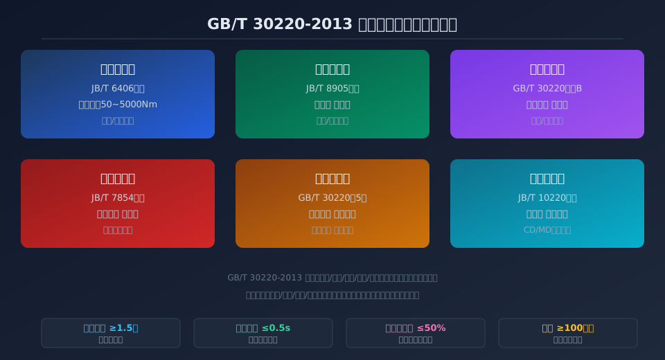
GB/T 30220 Scope of Application and Brake Classification System
GB/T 30220-2013 applies to brake products fitted on Bridge Crane, Gantry Crane, Tower Crane, Mobile Crane, and various special-purpose cranes. The standard classifies brakes into five basic types by structural form: shoe, disc, band, hydraulic, and electromagnetic. Each type is accompanied by typical structural drawings and key dimensional parameters in the appendices.
Shoe brakes are the most widely used type, accounting for over 65% of the industrial crane market, with typical representatives being the YWZ series hydraulic thruster shoe brakes and the ZWZ series electromagnetic shoe brakes. Disc Brakes, known for their fast Response time and superior heat dissipation, are widely applied in Hoisting and Luffing mechanisms. Band brakes, with their compact structure and large wrap angle, are commonly found in Slewing mechanisms and light-duty travel mechanisms.
The standard places particular emphasis on the safety function classification of brakes: Hoisting and Luffing mechanisms fall under Safety Brake classification, requiring Fail-Safe design—meaning the brake automatically engages upon power loss or hydraulic failure. Travel and Slewing mechanisms fall under Service Brake classification, where controlled braking is permitted. In Kelude Heavy Industry's Bridge Crane products, the Hoisting mechanism comes standard with YWZ5 series hydraulic block brakes, while the Crane Travel Mechanism uses YPZ series Disc Brakes. All brakes pass both the Type Test and routine factory testing required by GB/T 30220.
8 Core Brake Performance Indicators Explained
Chapter 5 of GB/T 30220-2013 specifies eight core performance indicators for brake products, each directly affecting the operational safety and reliability of the brake:
① Braking torque: The standard requires that under rated operating conditions, the braking torque must be no less than 1.5 times the rated static load torque. For Hoisting mechanisms, this factor determines whether the load can be reliably held suspended at full rated load.
② Brake Response time: The time from brake signal initiation until braking torque reaches 90% of its rated value. The standard specifies that emergency braking Response time must not exceed 0.5 seconds. Hydraulic brakes additionally require testing of the hydraulic system pressure buildup time.
③ Friction coefficient stability: Over the temperature range of 100°C to 250°C, the dynamic friction coefficient of the brake friction material must not deviate by more than ±25% from its ambient-temperature value. Appendix C of the standard provides the specific test method and acceptance criteria for friction coefficient thermal degradation.
④ Wear life: After 1,000,000 dynamic braking Duty Cycles under rated conditions, the remaining Friction lining thickness must be no less than 50% of the original thickness. This serves as the core basis for determining when Friction linings have reached their replacement threshold.
⑤ Noise level: The A-weighted Sound pressure level during brake engagement and release must not exceed 85dB(A), measured at a distance of 1 meter from the brake. The standard references GB/T 3768 as the acoustic measurement method.
⑥ Temperature rise limit: Under continuous duty operation, the maximum surface temperature of the Brake wheel (or Brake Disc) must not exceed 150°C, and Hydraulic Oil temperature must not exceed 80°C. The standard requires a continuous braking temperature rise test of no less than 2 hours.
⑦ Insulation Resistance: For electromagnetic brake coils, the Insulation Resistance to ground must be no less than 20MΩ in the cold state and no less than 1MΩ in the hot state. The dielectric test voltage is 2 times the rated voltage plus 1000V.
⑧ Protection Rating (IP): The brake housing Protection Rating must be no lower than IP54, and IP65 for outdoor applications, in accordance with the GB/T 4208 enclosure protection standard.
Kelude Heavy Industry performs 100% individual Inspection of all eight indicators before shipment, ensuring that every crane leaving the factory has a braking system fully compliant with all technical requirements of GB/T 30220-2013.
5-Step Brake Selection Verification Method
Based on the selection guidelines in Appendix A of GB/T 30220-2013, engineering practice typically employs a 5-step verification method for brake selection, ensuring the chosen brake meets both functional requirements and the Safety factor margins specified by the standard:
Step 1: Determine the duty classification. Based on the actual operating environment and TSG 51 Safety Technical Specification for Special Equipment requirements, establish the crane Work Duty (A1 to A8) and mechanism duty classification (M1 to M8)—these are the fundamental input parameters for selection.
Step 2: Calculate the equivalent braking torque. Taking the Hoisting mechanism as an example, account for the combined effects of the lifting load, acceleration inertia forces, wind loads (for outdoor use), and slope loads to calculate the equivalent steady-state braking torque, then apply a 1.5x Safety factor.
Step 3: Match the brake type to the mechanism function. Hoisting/Luffing mechanisms: prioritize Fail-Safe hydraulic block brakes or Disc Brakes. Travel mechanisms: electromagnetic or hydraulic brakes are suitable. Slewing mechanisms: band or Disc Brakes are recommended.
Step 4: Verify thermal capacity. Calculate the equilibrium temperature of the brake under continuous Duty Cycle operation, ensuring the Brake Disc/Brake wheel surface temperature does not exceed 150°C. If thermal capacity is insufficient, upgrade the brake specification or add auxiliary cooling measures.
Step 5: Validate through testing. After selection, perform no fewer than 3 full-load dynamic braking tests per Chapter 6 of GB/T 30220, confirming that braking distance, braking time, and braking torque all fall within design limits before commissioning.
This 5-step selection method has been validated in Kelude Heavy Industry's Bridge Crane engineering practice, reducing brake selection errors by more than 80%.
Brake Installation and Routine Maintenance Technical Points
Installation quality directly affects brake performance and service life. Chapter 7 of GB/T 30220 sets explicit requirements for installation and commissioning. Installers must pay close attention to the following technical points:
The contact area between the Brake wheel and Brake shoe must be no less than 70% of the theoretical contact area, with the Contact pattern evenly distributed. During installation, a 0.05mm feeler gauge must be used to check the Brake Clearance between the Brake shoe and Brake wheel. The standard clearance value is adjusted within the range of 0.6 to 1.2mm depending on the brake specification.
Hydraulic brakes require a bleeding procedure after installation to ensure no residual air remains in the Hydraulic Pipeline. After bleeding, check the hydraulic thruster stroke; the deviation between actual and rated stroke must be controlled within ±2mm. Following installation, perform no fewer than 10 no-load action tests to confirm smooth, jam-free operation.
For routine maintenance, a four-tier inspection system—daily, weekly, monthly, and Annual Inspection—must be established for brakes in accordance with Chapter 8 of GB/T 30220-2013 and TSG 51 Safety Technical Specification for Special Equipment.
Daily Inspection: focus on visual inspection and electromagnet temperature.
Weekly Inspection: measure Friction lining wear and Brake Clearance.
Monthly Inspection: perform full-load braking performance testing.
Annual Inspection: commission a qualified inspection body to re-run Type Test items. Kelude Heavy Industry offers factory-authorized Annual Inspection services to keep brakes in optimal operating condition.
Shoe Brake vs. Disc Brake Parameter Comparison Table
Kelude Heavy Industry: Overhead Crane & Gantry Crane Solutions
Kelude Heavy Industry specializes in the design, engineering, and manufacturing of heavy-duty overhead cranes, gantry cranes, and electric hoists. Our equipment is built to meet international standards, ensuring reliable performance in demanding industrial environments across the United States and Europe.
Frequently Asked Questions
Q: What is the typical lead time for a standard overhead crane?
A: For a standard single-girder crane up to 10 short tons, the lead time is typically 6-8 weeks from receipt of order and approved drawings. Double-girder cranes and custom configurations may require 10-12 weeks.
Q: Do you provide installation and commissioning services?
A: Yes, we offer a complete turnkey service including installation, testing, and commissioning by our certified engineering teams. We also provide operator training and comprehensive after-sales support.
Q: Can your cranes be adapted for existing runways or buildings?
A: Absolutely. We frequently design cranes to fit existing runway beams and building constraints. Our engineering team will conduct a site survey to ensure a perfect fit and optimal performance.
Brake Inspection Items and Standard Requirements
| Inspection Item | GB/T 30220Corresponding Clause | Conformity Assessment Standard |
|---|---|---|
| Visual and Dimensional Inspection | Clause6.1Item | Surface Free of Crack, Porosity, Porosity |
| Braking torque Test | Clause6.2Item | ≥1.5Times Ratedstatic Load Torque |
| Response time Test | Clause6.3Item | ≤0.5s(Emergency Braking) |
| fatigue life Test | Clause6.4Item | 100After 10,000 Cycles Wear≤50% |
| Temperature Rise Test | Clause6.5Item | Brake wheel≤150℃ |
| Electrical Insulation Test | Clause6.6Item | Cold State≥20MΩ |
A: 1.5×
Minimum Safety Factor
≤0.5s
Emergency Brake Response
1M Cycles
Fatigue Life Baseline
≤150°C
Brake Wheel Temp. Rise Limit
50%
Friction Lining Wear Limit
IP54
Minimum Protection Rating
Related Reading
Brakes are the core safety component of any crane system, and their technical standards are closely tied to design codes and safety supervision. The following articles explore brake standards and practical maintenance techniques from different angles:
• 5 Common Causes of Gearbox Oil Leaks on Overhead Cranes (and Fixes) — Field-tested maintenance tips for crane drive systems
• GB/T 22414-2008: Technical Conditions and Inspection of Hoisting Mechanism Braking Systems — Dual-brake configurations and redundant safety design for hoisting mechanisms
• JB/T 8905.1-2014: Hydraulic Disc Brake Standard Explained — Structural parameters of hydraulic brakes and hydraulic system matching
• TSG 51-2023: Rules for the Management of Special Equipment — Periodic inspection intervals and brake safety check requirements for cranes
Frequently Asked Questions
Q: What safety factor does GB/T 30220 require for hoisting mechanism brakes?
A: Clause 5.1 of GB/T 30220-2013 specifies a minimum braking torque safety factor of 1.5 for hoisting mechanism brakes — meaning the brake must generate at least 1.5 times the static torque of the rated lifting load reflected to the brake shaft. In practice, a factor of 1.8 to 2.0 is typically selected to account for dynamic load impact and braking torque decay as friction linings wear. This requirement aligns with Clause 7.3.2 of GB/T 3811-2008 (ISO 4301) and the TSG 51-2023 Safety Technical Specification for Special Equipment, ensuring adequate safety redundancy when the crane holds a full load suspended.
Q: What's the difference between shoe brakes and disc brakes on cranes, and how do I choose?
A: Shoe brakes (YWZ series) use brake shoes that wrap around a brake wheel, offering a braking torque range of 50–5,000 Nm. They are low-cost, easy to maintain, and well suited for the hoisting and travel mechanisms of overhead cranes. Disc brakes (YPZ series) respond faster (0.15–0.3 s) and dissipate heat more effectively, with a torque range of 100–8,000 Nm — ideal for luffing mechanisms and hoisting applications that involve frequent braking or require rapid response. At equal braking torque, disc brakes are more compact but cost roughly 30–50% more than shoe brakes; shoe brakes offer better value but run hotter. Kelude Heavy Industry prioritizes disc brakes on large-capacity overhead cranes to maximize braking reliability.
Q: What causes load slipping during braking, and how do I fix it?
A: Load slipping (the load slowly descending while the brake is engaged) usually has one of three root causes: ① Worn friction linings — when remaining thickness drops below 50% of the original, the brake can no longer generate sufficient torque; replace the linings immediately. ② Contaminated brake wheel surface — oil or moisture can drop the friction coefficient from 0.35 to below 0.15; clean the wheel surface with a dedicated solvent and trace the source of contamination. ③ Fatigue or fracture of the brake spring — check the spring preload with a torque wrench against the values specified in Appendix D of GB/T 30220. Never insert foreign material between the friction surfaces as an emergency workaround — this is strictly prohibited.
Q: What is the standard brake clearance for electric hoist cone brakes, and how do I adjust it?
A: For cone brakes on electric hoists, the standard brake clearance between the cone and the brake wheel is 0.5–1.0 mm. To adjust, loosen the locknut on the adjusting nut, rotate the nut to achieve the correct clearance (clockwise reduces it, counterclockwise increases it), then retighten the locknut. After adjustment, verify that the brake engages and releases smoothly without dragging, and confirm the braking torque meets the requirements of the hoist's rated capacity. Always refer to the manufacturer's manual for the specific model, as clearance values may vary.
A: Per Appendix B of GB/T 30220-2013 and JB/T 10220-2014, the normal brake clearance for the cone brake on a CD1-type electric hoist is 0.6–1.0 mm; for the MD1-type two-speed electric hoist, it is 0.8–1.2 mm. When the clearance exceeds 1.5 mm, adjustment is required: first loosen the lock nut, then rotate the adjusting bolt to reduce the clearance to the standard value. Use a feeler gauge to check uniformity at three equally spaced points around the circumference, then retighten the lock nut and recheck with a 0.05 mm feeler gauge—it should not be able to enter the gap. After adjustment, perform three full-load braking tests to confirm there is no load slipping.
