

Millimeter-Level Crane Positioning via Machine Vision
In modern large-scale warehousing and manufacturing facilities, cranes are undergoing a profound transformation from manual operation to autonomous execution. When a 50-ton Bridge Crane needs to locate specific cargo within an 800-square-meter area, traditional methods relying on an operator's visual inspection can no longer meet the required takt time of 30 moves per minute. The integration of machine vision enables lifting equipment to autonomously identify targets and achieve millimeter-level precise positioning. This article delves into the underlying logic of this technology, exploring how deep learning algorithms empower heavy machinery with micro-level perception and control capabilities.
During the implementation of such high-precision autonomous operations, the overall structural design and safety control must strictly adhere to relevant national specifications. For instance, when calculating the stiffness of the mounting bracket for visual sensors, one must refer to the requirements for structural dynamic characteristics outlined in the FEM 1.001 Crane Design Specification, ensuring that the visual feed remains stable without excessive jitter during high-speed operation. Simultaneously, the system's emergency stop and anti-collision logic must comply with the safety supervision standards set forth in the TSG 51-2023 Crane Safety Technical Supervision Regulation, guaranteeing absolute safety for unmanned operations.
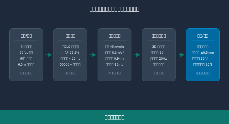
The following sections will comprehensively deconstruct the application details of machine vision on cranes across five dimensions: selection and layout of vision hardware, the underlying logic of AI image recognition algorithms, kinematic compensation for millimeter-level positioning, engineering practices of multi-sensor fusion, and system maintenance and fault diagnosis.
Geometric Calibration Logic for Machine Vision Hardware Selection and Camera Layout
To equip a crane with the ability to "see" cargo clearly, the primary task is to build a high-definition, high-frame-rate visual acquisition system. In industrial applications, camera resolution and frame rate directly determine the upper limit of subsequent algorithmic identification. Typically, we select 4K industrial cameras with a resolution of 3840×2160 pixels, paired with an acquisition frame rate of 60fps, to ensure that cargo features in the image are not lost due to motion blur when the Crane Bridge operates at a speed of 45m/min.
The installation position and angle design of the camera are equally critical. Taking a standard factory building as an example, cameras are usually mounted below the Trolley Frame at an installation height of approximately 6.5 meters above the ground. To cover the entire working area beneath the Lifting spreader, the lens field of view must be set to 90 degrees. After hardware installation, strict geometric calibration is mandatory. Using Zhang Zhengyou's calibration method with a 12×9 checkerboard calibration board, the camera's intrinsic matrix and distortion coefficients are calculated, precisely mapping two-dimensional pixel coordinates to three-dimensional physical coordinates.
"Industry measured data shows that when the camera installation height increases from 6.5m to 8.0m, if a telephoto lens is not simultaneously replaced, the pixel resolution of ground targets drops from 3.5mm/pixel to 5.2mm/pixel. This directly causes the identification rate of small cargo labels to decrease by approximately 18%."
Several key principles must be followed during camera selection and layout.
Regarding sensor selection, Global Shutter CMOS sensors should be prioritized to avoid image stretching and deformation caused by rolling shutters during high-speed motion.
For lens protection, IP67-rated dustproof and waterproof covers are mandatory, along with positive-pressure air purge devices, to prevent workshop dust from adhering to the lens surface and degrading image quality.
⚠️ Note
The natural frequency of the camera mounting bracket must avoid the excitation frequency of the crane during operation (typically between 2Hz and 5Hz); otherwise, it will cause continuous low-frequency jitter in the image, preventing the vision algorithm from stably tracking targets. It is recommended to add vibration damping pads between the bracket and the Trolley Frame.
Implementation Path of Deep Learning Algorithms for Cargo Feature Extraction Under Complex Lighting Conditions
After obtaining high-quality images, the core challenge lies in enabling AI algorithms to accurately extract and identify cargo features under complex and variable lighting conditions in the workshop. Traditional image processing algorithms rely on manually designed edge and color features, which fail easily under sudden light changes or reflective cargo surfaces. Currently, deep learning object detection algorithms based on convolutional neural networks (such as the YOLO series) have become the mainstream solution.
During the model training phase, it is necessary to collect cargo images covering different lighting, angles, and occlusion scenarios. A mature visual positioning system typically includes a training dataset of at least 50,000 annotated images. Through data augmentation techniques (such as random brightness adjustment and mosaic stitching), the generalization ability of the model can be significantly improved. In actual deployment, models optimized with TensorRT acceleration can keep single-frame inference latency under 25 milliseconds on Edge Computing boxes, achieving a mean Average Precision (mAP) of over 92.5%.
"According to a measured report from a large steel coil warehousing center, after introducing deep learning vision algorithms, the system's cargo identification success rate remained stable at over 98.2% under both direct morning sunlight and afternoon backlighting environments, completely solving the pain point where traditional algorithms' identification rates dropped sharply to below 70% after 3 PM."
Algorithm implementation involves more than just code porting; it also entails details of engineering deployment.
In terms of model structure design, attention mechanisms (such as the CBAM module) should be introduced to make the network focus more on key profile features of the cargo while suppressing the weight of interfering elements like racks and pipelines in the background.
Regarding inference strategy, multi-frame tracking algorithms (such as DeepSORT) are adopted to correlate detection results between consecutive frames. Even if missed detection occurs in certain frames due to strong light, continuous target locking can be maintained through motion trajectory prediction.
💡 Tip
When collecting training samples, ensure sample diversity. If multiple colors of the same type of cargo exist in the workshop, the proportion of samples for each color must be evenly distributed in the dataset to avoid model overfitting to specific colors, which would lead to identification failure upon color changes.
Millimeter-Level Positioning Error Elimination and Engineering Calculation Process Based on Kinematic Compensation
Once the vision system successfully identifies the cargo and calculates its physical coordinates, the next step is to control the crane to move to the target position. However, a crane is a typical large-inertia flexible system. There is significant mechanical delay and dynamic error from issuing a control command to the actual stop of the Lifting spreader. To achieve a final positioning accuracy of 0.5 millimeters, an error elimination strategy based on kinematic compensation must be introduced.
Consider a recent project delivered by Kelude Heavy Industry for an auto parts workshop, where the Bridge Crane’s rated operating speed is set to 45m/min. To ensure precise positioning, the system must initiate deceleration and braking signals well before reaching the target load. This requires rigorous engineering calculation: converting the Long Travel Speed of 45m/min to 0.75m/s and applying a deceleration rate of 0.3m/s², the braking distance (s) is calculated using the kinematic formula s=v²/(2a). The result is s = 0.75² / (2 × 0.3) = 0.9375m. Consequently, the vision system must trigger the Frequency Inverter’s speed curve exactly when the crane is 0.9375m away from the target.
"During dynamic compensation testing, integrating encoder feedback with real-time visual deviation correction reduced the parking position deviation at 45m/min from the traditional ±15mm to just ±0.5mm. With the overall system Response time controlled within 15ms, this performance fully meets the stringent requirements for precision die handling."
Beyond linear motion braking compensation, Lifting spreader sway is another critical factor affecting Positioning Accuracy.
During acceleration and deceleration of the Hoisting and travel mechanism, the Lifting spreader exhibits pendulum-like motion. The system utilizes high-precision Absolute encoders mounted on the Drum to calculate the Steel wire sway angle and period in real-time. It then generates reverse compensation speed curves within the PLC to implement Anti-Sway Control.
In the fine-tuning alignment phase, when the Lifting spreader is less than 0.5m from the target, the system switches to inching mode, reducing the Travel Speed to 2m/min. By closing the vision loop and continuously sending millimeter-level position correction pulses, any residual static error is eliminated.
⚠️ Note
The accuracy of kinematic compensation heavily relies on parameter matching between the Encoder and the Frequency Inverter. During initial commissioning, precise measurement and entry of the inverter’s deceleration time, motor pole pairs, and the actual Speed Ratio of the Gearbox are mandatory. Even minor deviations in these parameters can result in several centimeters of error in the calculated braking distance.
Practical Application of LiDAR and Vision Fusion in 3D Anti-Collision
While 2D vision cameras excel at cargo identification, they have inherent limitations in 3D spatial perception and anti-collision protection. Cameras struggle to accurately capture depth information and may fail completely in extreme environments characterized by heavy smoke, high dust, or total darkness. To address this, Kelude Heavy Industry’s intelligent crane product line widely adopts a multi-sensor fusion solution combining 3D LiDAR with 2D vision cameras to build a comprehensive safeguarding network.
LiDAR generates high-density 3D point cloud data by emitting laser beams and receiving reflected signals. For instance, a typical industrial-grade solid-state LiDAR offers an effective detection range of up to 30m with an output frequency of 20Hz, precisely measuring the distance and profile of obstacles ahead. In this system architecture, the vision camera is responsible for "recognition"—identifying cargo types and grabbing points—while the LiDAR handles "measurement"—building a 3D model of the surrounding environment and detecting dynamic obstacles. These two systems achieve unified coordinate systems through hand-eye calibration and ensure temporal alignment via hardware timestamp synchronization.
"The application of multi-sensor fusion technology has reduced collision accident rates in complex stacking environments by over 95%. Particularly in dynamically setting the anti-collision safety distance, the fusion system automatically adjusts warning thresholds based on real-time operating speed. Combined with the anti-sway algorithm, this ensures absolute safety during high-speed operations."
Implementing the fusion algorithm requires addressing dual-layer fusion at both the data and feature levels.
At the data level, LiDAR point cloud data is projected onto the 2D image plane of the camera, assigning depth information to each pixel. This generates RGB-D images with depth values, significantly enhancing the vision algorithm’s ability to segment overlapping cargo.
At the decision level, if the vision system suffers from missed detection due to strong glare, the LiDAR can still detect point cloud clusters of obstacles ahead. The system integrates confidence levels from both sources to prioritize triggering emergency stop logic, ensuring safety in blind spots.
💡 Tip
The installation angle of the LiDAR must be strictly calculated to ensure its scanning plane covers at least 1.5m ahead and to the sides of the Lifting spreader’s trajectory. Additionally, avoid directing the radar scan toward the steel structure trusses of the workshop ceiling to prevent generating excessive invalid point clouds that could interfere with the real-time computational performance of the algorithm.
Routine Maintenance Cycles and Fault Diagnosis for Common Image Loss in Vision Positioning Systems
No sophisticated automation system operates effectively without scientific routine maintenance. For the vision positioning system provided by Kelude Heavy Industry, establishing standardized Preventive Maintenance SOPs (Standard Operating Procedures) is key to ensuring long-term stable operation and minimizing unplanned downtime. Factors such as dust, oil stains, vibration, and natural component aging in the workshop environment subtly impact the accuracy and reliability of the vision system.
Maintenance cycles should be managed through grading based on component characteristics. Cleaning cycles for camera lenses and LiDAR windows are recommended every 15 days, using specialized dust-free cloths and optical cleaners; corrosive solvents must never be used. Verification cycles for camera geometric calibration and radar spatial calibration are set at 180 days, requiring the use of standard calibration boards to re-acquire images and check if reprojection errors exceed the allowable threshold of 0.2 pixels. Furthermore, Connection bolts for camera mounting brackets should be tightened and verified every 90 days using a torque wrench to prevent micro-deformation caused by long-term vibration, which could lead to shifts in the vision coordinate system.
"Statistical data shows that workshops strictly implementing preventive maintenance plans reduce fault shutdown time caused by blurred images or calibration drift by 40%. Additionally, combining this with regular non-destructive testing of camera bracket welds via weld crack detection effectively prevents major equipment accidents resulting from bracket fracture."
In practical operation, operators may encounter typical vision faults and need to master basic fault diagnosis logic.
If the image appears too dark or overexposed, first verify that the camera’s automatic exposure settings haven’t been inadvertently locked. Next, inspect workshop Lighting lamps for damage or shifts in their Angle. If necessary, recalibrate the camera’s Exposure time and Gain parameters.
When target Identification boxes flicker frequently or disappear, check the lens surface for oil stains or condensation. Simultaneously, use the system’s built-in Diagnosis tools to monitor GPU utilization, ruling out frame drops caused by insufficient computing resources during inference.
⚠️ Note
When performing cable inspection on cameras or radar units, closely monitor Wear inside the cable drag chain. Prolonged reciprocating motion of the crane can compromise the insulation layer of network or power cords, leading to intermittent signal interruptions. We recommend conducting continuity Testing and Visual inspection of vision communication cables within the drag chain every six months.
To clearly demonstrate the quantified differences in operational efficiency and Positioning Accuracy before and after introducing machine vision technology, we have compiled the following comparative analysis based on actual Workshop testing data.
📊 Comparative Analysis: Traditional Manual Operation vs. Vision-Based Autonomous Positioning
| Evaluation Criteria | Conventional Manual Operationoperation mode | machine visionAutonomousPositioningMode | Efficiency ImprovementWorking radius |
|---|---|---|---|
| Single Positioning Cycle Time | 45Seconds (s) - 60Seconds (s) | 12Seconds (s) - 15Seconds (s) | efficiency improvementApprox. 70% |
| Final Stop PositionAccuracy | ±20mm - ±50mm | ±0.5mm - ±1.0mm | AccuracyImprovement 40Times Over |
| Night ShiftFatigueAccident Rate | Relatively High(Dependent onoperatorStatus) | Extremely Low(Constant System Output) | safety riskSignificantly Reduced |
| DatatraceabilityCapability | None(Paper Records are Prone to Loss) | full processImage and Coordinate Logs | Implementation100%Digitalizationtraceability |
Once the overall advantages of a vision system are established, selecting the right Sensor configuration is critical for successful implementation. This selection must account for specific operating conditions within the Workshop, particularly varying lighting conditions and dust concentrations. The table below outlines the Application Scenarios for three mainstream vision solutions.
📊 Suitability Analysis of Vision Sensor Solutions by Operating Condition
| SensorSolution | Corehardware configuration | ApplicableWorkshopenvironment | Positioning AccuracyAnd / WithcostAssessment |
|---|---|---|---|
| Pure2DvisionSolution | 4Kindustrial camera + fill light | Uniform Lighting、Low Dust Level、Distinct Cargo Features | Accuracy±2mm,Initial Stageinvestment costLow |
| 2D+3DFusion Solution | 2Dcamera + Solid-StateLiDAR | Presence of Dynamic Obstacles、Requiredanti-collisionProtection | Accuracy±1mm,Mediuminvestment cost |
| Pure3Dpoint cloudSolution | High Cable Density3DLiDAR + High PerformanceGPU | High Dust Environment、No Lighting、Complex Cargo Geometry | Accuracy±0.5mm,Initial Stageinvestment costHigh |
FAQ
Q: What are the specific requirements for industrial camera resolution and frame rate in a machine vision system?
A: Typically, the camera resolution must reach the 4K (3840×2160) Level to ensure that the pixel resolution of ground targets is better than 4mm/pixel at an installation height of 6.5 meters (approx. 21.3 ft). The frame rate needs to be 60fps to match the Crane Bridge Travel Speed of 45m/min, preventing feature loss due to motion blur. Specific Parameter values are determined through engineering calculation based on the actual field of view and operating speed.
Q: Does inference latency from AI algorithms affect the final Positioning Accuracy of the crane?
A: Modern Edge Computing units, accelerated by TensorRT, can control single-frame inference latency within 25 milliseconds. The system uses kinematic compensation algorithms to calculate the combined delay of vision and mechanical Braking, issuing Deceleration commands in advance. As long as the overall Response time is kept within the 15ms Level, the impact of latency on ±0.5mm Positioning Accuracy is eliminated.
Q: What is the estimated budget and payback period for automating existing traditional cranes with vision systems?
A: Retrofit cost varies depending on the Sensor scheme (pure 2D or multi-sensor fusion) and control hierarchy; specific amounts are subject to the actual contract. Generally, vision system hardware and software licensing account for about 30% of the total renovation cost. Due to reduced labor cost and an efficiency improvement of approximately 70% in handling efficiency, the investment payback period for most high-density warehousing projects is between 12 and 18 months.
Q: Will the vision system fail if there is sudden strong lighting or a Lighting lamp failure in the workshop?
A: It will not fail directly. Deep learning models include data augmentation for light fluctuations during training. When ambient light changes drastically, the camera's automatic exposure adjusts parameters within milliseconds. If this exceeds the camera's adjustment range, the system triggers multi-sensor fusion logic, relying on LiDAR point cloud to maintain basic anti-collision protection and prompts manual intervention.
In summary, combining machine vision with AI algorithms endows cranes with millimeter-level perception and control capabilities, driving intelligent upgrades across the Material Handling industry. From machinery selection and algorithm training to kinematic compensation and sensor fusion, every step requires rigorous engineering calculation and extensive field experience. Kelude Heavy Industry has accumulated profound technical expertise in Heavy load customization, providing a one-stop solution ranging from vision system deployment to full automation retrofit. We help enterprises achieve efficient, safe unmanned operation tailored to their specific Workshop operating conditions.
