

Crane Electrical System Field Commissioning: From Basics to Advanced
On-site commissioning of the crane electrical system is the final critical step in the installation process, covering PLC program download and verification, VFD parameter tuning, sensor calibration, and communication bus testing. Kelude Heavy Industry employs a Siemens S7 series PLC + G120 VFD + PROFINET architecture. This article walks through the entire commissioning workflow, from pre-commissioning prerequisites to integrated machine testing.
On-site commissioning of the electrical system is the final step in crane installation and the key to ensuring the equipment operates as designed. Commissioning quality directly determines operational reliability, communication stability, and the integrity of safety protection functions. Kelude Heavy Industry cranes use a Siemens S7 series PLC, G120 VFDs, and a PROFINET bus architecture. On-site commissioning covers PLC program download and verification, per-mechanism VFD parameter tuning, sensor calibration, and communication bus testing. The applicable standards are IEC 60204-32 (Electrical safety of machinery) and IEC 61800 (Adjustable speed electric drive systems).
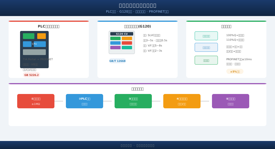
Pre-Commissioning Prerequisites and Checks
Before electrical commissioning begins, the following prerequisites must be confirmed: main circuit power cable termination is complete and phase sequence is correct (verified with a phase rotation tester); the 24VDC control circuit power supply is energized and stable (±5%); the VFD main circuit input voltage matches the nameplate rating (380V±10%); PLC module indicators show no fault alarms; all Emergency Stop Buttons are released; and the handheld programmer/programming PC is ready for communication. It is recommended to measure the Insulation Resistance of the main and control circuits with a 500V insulation tester before commissioning; the resistance to ground must be ≥1MΩ.
PLC Program Download and Logic Verification
The PLC program is downloaded using Siemens TIA Portal software via the PROFINET interface (with the IP address set to the same subnet as the programming PC). Before downloading, verify that the program version matches the design drawings. After the download, perform a CPU memory reset to clear any residual old data. Program verification proceeds in the following order: 1) Check that the module configuration matches the actual hardware (order number and firmware version); 2) Verify that the I/O address mapping corresponds to the wiring diagram; 3) Functionally verify the control logic for the Hoisting mechanism, crane travel mechanism, and trolley mechanism (Inching / Jog Mode, coordinated operation, speed switching); 4) Verify that the safety protection logic (Emergency Stop, limit switch activation, Overload Alarm) produces the expected results. All verification items must be recorded on the commissioning checklist.
VFD Parameter Tuning by Mechanism
VFD parameters are tuned separately for the Hoisting mechanism, crane travel mechanism, and trolley mechanism. Kelude Heavy Industry's commissioning procedure requires SLVC Vector Control for the Hoisting mechanism and V/f control for the crane travel and trolley mechanisms. Hoisting mechanism (G120 VFD): Uses sensorless SLVC Vector Control; acceleration time set to 3–5 seconds (use the higher value for heavy loads); brake release delay of 0.3 seconds; Brake application delay of 0.5 seconds; the brake-open confirmation signal is wired to a VFD Digital Input. Crane travel mechanism: Uses V/f control; acceleration time set to 5–8 seconds (to prevent overcurrent on high-inertia loads); S-curve smoothing coefficient of 0.5 seconds for acceleration/deceleration. Trolley mechanism: Uses V/f control; acceleration time set to 2–3 seconds; symmetrical tuning for forward and reverse directions.
The comparison table below details each parameter:
| Parameter | Hoisting Mechanism | Crane Travel Mechanism | Trolley Mechanism |
|---|---|---|---|
| Control Mode | SLVC Vector Control (sensorless) | V/f control | V/f control |
| Acceleration Time | 3–5 s (higher for heavy loads) | 5–8 s | 2–3 s |
| Brake Release Delay | 0.3 s | — | — |
| Brake Application Delay | 0.5 s | — | — |
| S-Curve Smoothing Coefficient | — | 0.5 s | — |
| Mechanism | Control Mode | acceleration time | Braking Time Delay | Critical Parameter |
|---|---|---|---|---|
| Hoisting mechanism | SLVCVector Control | 3~5s | 0.5s | P2910/P2920brake control |
| crane travel mechanism | V/f Control | 5~8s | 1.0s | P1120/P1121 SCurve Smoothing |
| trolley mechanism | V/f Control | 2~3s | 0.8s | Symmetric Tuning with Consistent Forward/Reverse Direction |
After parameter tuning, perform a no-load test run: operate each mechanism at low speed (5Hz), medium speed (25Hz), and high speed (50Hz) for 5 minutes each. Verify that current values are balanced (three-phase current deviation ≤10%), that the running direction matches the control command, and that the brake open/close timing sequence is correct. Record the no-load current values of each mechanism as baseline data for comparison during subsequent load tests.
Sensor and Encoder Calibration
Overload Limiter Calibration: Hang the rated load (100%Q) on the hook, then adjust the zero and gain potentiometers on the limiter indicator until the displayed value matches the actual load. Next, load to 110%Q to confirm the alarm output (audible and visual alarm) activates, then load to 125%Q to confirm the power-off shutdown output triggers. After calibration, verify three load points (30%Q, 70%Q, 100%Q) using standard test weights; the indication error should be within ±5%.
Lifting Height Encoder Calibration: Raise the hook to the upper limit position (with the lifting spreader top at least 200mm from the upper limit switch), then zero the encoder to establish the reference point. Lower the hook to the lower limit and record the maximum travel distance. After calibration, verify position accuracy at 0%, 25%, 50%, 75%, and 100% of the travel range. Calibrate the travel encoders (crane bridge and trolley) using the same method.
Communication Bus Testing
PROFINET bus testing includes: checking the network status LEDs on all IO devices (steady green indicates normal operation), pinging each slave station's IP address to confirm connectivity, and using the TIA Portal diagnostic function to scan the network and verify that all devices are online. The communication cycle time (bus cycle time) must not exceed 10ms to ensure real-time response of safety commands.
This topic is a core part of the Complete Guide to Crane Installation, Commissioning, and Acceptance series. For the next stage of installation and commissioning, refer to Limit Switch and Safety Device Commissioning: Hoisting Limit / Travel Limit / Overload Limiter Calibration Procedures.
Frequently Asked Questions (FAQ)
Q: What should I do if the VFD displays fault code F7800 after power-up?
A: F7800 indicates DC bus undervoltage. Common causes include: low incoming line voltage at the main circuit (below 360V), a damaged rectifier module, an open pre-charge resistor, or a contactor that fails to close. Kelude commissioning technicians check the incoming line voltage, DC bus voltage (normally approximately 540V DC), pre-charge contactor status, and rectifier bridge output in sequence, then resolve the issue following standard fault diagnosis procedures.
Q: What should I do if the brake fails to open when the hoisting mechanism is running?
A: Common causes of a brake failing to open include: a burned-out brake rectifier module, abnormal brake coil resistance (normal range is approximately 50–200Ω depending on the model), mechanical binding in the brake, missing 24VDC control power, or the PLC not issuing the brake-open command. Check the brake power supply and control signal circuits in sequence. Never operate the hoisting mechanism with a faulty brake.
Q: How do I troubleshoot a PROFINET slave station that keeps dropping off the bus?
A: Follow these steps to troubleshoot a slave station going offline: 1) Check the status LEDs on the network switch port and the slave station's Ethernet port (whether the green light is flashing); 2) Check whether the RJ45 connector is loose or damaged; 3) Use TIA Portal diagnostics to check whether the slave station is online; 4) Power-cycle the slave station and observe whether communication recovers; 5) Verify that the bus termination resistor is set correctly (termination must be enabled on end devices).
Q: What should I do if the load limiter reading drifts during use after calibration?
A: Common causes of load limiter reading drift include: poor grounding of the sensor cable shield, loose sensor mounting causing load misalignment, or the indicator's ambient temperature exceeding its operating range. If the displayed value drifts by more than ±5% after calibration, recalibrate and investigate the causes listed above. As a safety device, the lifting capacity limiter should be sent for annual verification.
