

Crane Contactor Burnout: 6 Root Causes & Fixes
Key Point: The six root causes of frequent contactor burnout in cranes, ranked by occurrence, are: contact arc erosion (~55%), inter-turn short circuit of coil (~20%), dust and corrosive gas ingress (~15%), undersized contactor selection (~6%), control power supply fluctuation (~3%), and mechanical jamming (~1%). This article examines the mechanism, troubleshooting method, and preventive action for each root cause.
Role of Contactors in Crane Electrical Systems
Contactors are among the most critical switching devices in both the main circuit and control circuit of a crane's electrical system. In a typical bridge crane, the hoisting mechanism, crane travel mechanism, and trolley travel mechanism each incorporate 2 to 4 contactors for motor reversing and main power switching. For example, a 50t general purpose bridge crane is equipped with a 400A main circuit breaker, 160A hoist contactors ×2 (forward/reverse), 63A crane travel contactors ×2, and 25A trolley travel contactors ×2, plus control-circuit contactors supplying power to the PLC and sensors.
Contactors in crane service operate under extremely demanding conditions — the hoisting mechanism can cycle 120 to 240 times per hour, and the crane travel mechanism 100 to 200 times per hour. Every make and break must withstand motor inrush current (typically 5 to 7 times the rated current) and the back electromotive force surge during braking. Improper contactor selection or neglected maintenance leads to contact erosion, coil burnout, and potentially uncontrolled motion or safety incidents.
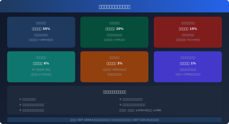
Six Root Causes of Contactor Burnout
Contactor burnout is rarely a single-cause failure; it results from the combined effects of electrical stress, environmental attack, and mechanical wear. The following breakdown addresses each root cause in descending order of failure frequency, covering the mechanism, on-site identification characteristics, and corrective action.
Contact Arc Erosion — The most common root cause, accounting for approximately 55% of field failures. Crane motors are inductive loads; when the contactor opens, the inductive energy discharges across the contact gap as a high-temperature arc reaching 3000–6000K. When a contactor operates in utilization category AC-4 (inching, plugging), the breaking current can reach 6 times the rated current, reducing contact life to 1/5–1/3 of that in AC-3 duty. Judgment criteria: measure contact resistance with a milliohm meter — normal values should be ≤50mΩ; when contact resistance exceeds 100mΩ, heating increases significantly and replacement is mandatory. On-site identification characteristics: pitted or mushroom-shaped contact surfaces (anode material transfer), discolored or carbonized plastic housing around the contacts.
Inter-Turn Short Circuit of Coil — Accounts for approximately 20% of failures. The contactor coil is wound with several hundred turns of magnet wire, typically rated for AC 220V/380V or DC 24V. Inter-turn short circuits result from: insulation degradation due to prolonged high temperature (coil life drops sharply when continuous temperature exceeds 130°C), moisture ingress reducing insulation resistance, and manufacturing defects causing weak-point breakdown. Once inter-turn shorting occurs, coil impedance drops and current rises, creating a positive feedback loop — short-circuit heating causes more turn-to-turn failures, eventually burning out the coil or causing fire. Judgment criteria: replace the coil when resistance deviates by more than ±15% from the nameplate value; insulation resistance between coil and core must be ≥1MΩ (measured with a 500V megohmmeter).
Dust and Corrosive Gas Ingress — Accounts for approximately 15% of failures, particularly prevalent in metallurgical, foundry, cement, and chemical workshops. Conductive dust (metal particles, carbon powder) entering the contactor settles on contact surfaces, causing poor contact and localized heating; corrosive gases (SO₂, H₂S, Cl₂, etc.) combine with atmospheric moisture to form acidic films that attack contacts and terminals. On-site identification: bluish-black or yellowish-green contact surfaces (oxide/sulfide films) that remain dark gray (non-metallic luster) after light sanding indicate severe oxidation. Protection requirements: per IEC 60204-32 (formerly IEC 60204-32), crane electrical cabinets installed indoors must have a protection rating of at least IP23, and IP54 in dusty workshops; sealed contactors should be selected for corrosive environments.
Undersized Contactor Selection — Accounts for approximately 6% of failures. Common errors include: using AC-3 rated contactors for AC-4 heavy-duty inching duty (crane hoist braking conditions approach AC-4), failing to perform thermal verification for duty classification S4/S5 (intermittent periodic duty), and substituting economy-grade contactors for industrial heavy-duty types. The contactor rated operational current Ie should be verified with the following redundancy: Ie ≥ 1.5 × motor rated current In (AC-3 duty), Ie ≥ 2.0 × In (AC-4 inching duty). For a 37kW hoist motor (In≈72A) operating under S4-40% duty (120 starts/stops per hour), select an AC-3 contactor rated at ≥110A (e.g., LC1D115 or 3RT1055), not an 80A unit matched directly to the motor current.
Control Power Supply Fluctuation — Accounts for approximately 3% of failures. Contactor coils have defined operating voltage requirements: AC coils must pick up reliably at 85%–110% of rated voltage and must drop out below 85% (undervoltage protection requirement per ISO 12480, formerly ISO 12480). When supply voltage is unstable (e.g., grid fluctuation exceeding ±15% in older workshops), the coil repeatedly picks up and drops out near the threshold voltage, generating arcing and mechanical shock that accelerate contact and coil damage. This is commonly seen in older facilities sharing a transformer, where voltage sag exceeds 20% during large motor starting. Corrective action: install a stabilized power supply or UPS in the control circuit; for critical mechanisms, select contactors with wide-voltage coils (e.g., AC/DC universal type with 0.7–1.3Ue operating range).
Mechanical Jamming and Core Contamination — Accounts for approximately 1% of failures and is the most easily overlooked. The contactor core is coated with anti-rust oil at the factory; over time, oil film attracts dust and forms a gummy deposit that prevents full core closure (increased residual air gap). When the core fails to close completely, coil impedance drops far below normal, causing current to surge (up to 3–5 times normal holding current) and rapidly burning out the coil. Additionally, a damaged or missing arc chute prevents effective arc extinction, leading to phase-to-phase short circuits and cascading burnout. Troubleshooting method: manually press the core — it should move smoothly without binding; listen during energization — a normal low-pitched "hum" is acceptable, while a sharp "buzz" indicates incomplete core closure.
Field Troubleshooting Procedure for Contactor Burnout
When a crane contactor burns out, follow this five-step troubleshooting method in sequence. Never replace the contactor and immediately re-energize without investigation — this often destroys the new contactor as well.
Step 1: De-energize and Verify Absence of Voltage — Open the crane's main circuit breaker and attach a "Do Not Close" warning tag. Use a multimeter to confirm zero voltage in both the main circuit and control circuit. Check whether the main circuit breaker or branch breakers have tripped — if the breaker did not trip but the contactor burned out, the breaker is undersized or its trip setting is too high.
Step 2: Visual Inspection — Open the contactor arc chute and examine the contact surfaces: a normal surface shows uniform silvery-white luster; bluish-black or rainbow-colored patches indicate severe oxidation; pitting or mushroom-shaped protrusions indicate arc erosion; completely melted or welded contacts indicate short-circuit current far exceeding the contactor's breaking capacity. Also inspect the arc chute for cracks or missing pieces, the coil housing for discoloration or swelling, and the terminal block for overheating marks (blackened copper terminals or discolored surrounding insulation).
Step 3: Electrical Measurement — Measure contact resistance with a milliohm meter or four-wire method (normal ≤50mΩ, critical at 100mΩ, replace beyond that). Measure coil resistance with a digital multimeter and compare to the nameplate value (within ±10% is acceptable; replace if deviation exceeds ±15%). Measure insulation resistance between coil and core (ground) with a 500V megohmmeter — must be ≥1MΩ. Readings below 0.5MΩ indicate moisture ingress or insulation breakdown; replace the coil and check the control cabinet's moisture-proof measures.
Step 4: Control Circuit Check — Verify that the control circuit supply voltage is within 85%–110% of the contactor coil rated voltage. If voltage is low, trace back to check whether the control transformer is adequately sized and whether the control circuit cable cross-section is sufficient (recommended minimum 1.5mm²; 1.0mm² may be used for runs up to 50m). Check whether surge suppression components are connected across the coil (RC absorber for AC coils, freewheeling diode for DC coils) — without protection, the back electromotive force generated at coil de-energization can reach several times the rated voltage, repeatedly stressing the coil insulation.
Step 5: Energization Test — After installing a replacement contactor, test pick-up and drop-out operation without load: measure pick-up time (typically 10–20ms for AC contactors) and drop-out time (10–15ms) with a stopwatch or oscilloscope; deviation of less than 30% from the manufacturer's specified values is acceptable. After confirming normal operation, connect the load and monitor the contactor housing temperature rise — after 30 minutes of continuous operation, the housing temperature rise must not exceed 65K (ambient temperature +65K is the upper limit; e.g., at 35°C ambient, housing ≤100°C) rise should not exceed 65K (ambient temperature +65K as the upper limit; e.g., at 35°C ambient, the housing should not exceed 100°C).
Contactor Selection and Protection Configuration Comparison
Kelude Heavy Industry: Overhead Crane & Gantry Crane Manufacturer
Kelude Heavy Industry is a professional manufacturer of overhead cranes, gantry cranes, and electric hoists. We provide a full range of material handling solutions, from single-girder and double-girder cranes to explosion-proof and low-headroom designs, serving industries such as manufacturing, logistics, and energy.
Frequently Asked Questions
Q: What is the lead time for a standard overhead crane?
A: Typical lead time is 4-6 weeks for standard models, depending on capacity and configuration. Custom engineered cranes may take 8-12 weeks.
Q: Do you provide installation services?
A: Yes, we offer professional installation and commissioning services in the US and Europe. Our technicians ensure your crane is set up safely and operates correctly.
Q: Can you supply spare parts for existing cranes?
A: Absolutely. We stock a wide range of spare parts for our own cranes and can also source parts for other brands. Contact us with your crane model and serial number for a quote.
Q: What safety standards do your cranes comply with?
A: Our cranes are designed and manufactured in accordance with ISO 4301 for crane classification, ISO 12480 for safe use, and IEC 60204-32 for electrical equipment. We can also certify cranes to other local standards upon request.
Preventive Maintenance to Prevent Contactor Burnout
A: Preventing contactor burnout is far more cost-effective than replacing failed units. The following four maintenance practices can reduce contactor failure rates by over 70%.
Regularly Measure Contact Resistance — Use a micro-ohmmeter to measure contact resistance on the contactors of critical mechanisms (hoisting and crane bridge travel) every quarter and track the trend. A rise in contact resistance from 50 mΩ to 80 mΩ, while still within acceptable limits, signals the onset of contact degradation. Such a trend warrants scheduling replacement during the next maintenance window to avoid unplanned downtime from sudden burnout.
Clean Dust and Inspect Seals — Every six months, open the contactor arc chute and blow out accumulated dust from the contact area using dry compressed air (≤0.3 MPa). Inspect the electrical cabinet sealing strips for aging — replace them if rebound elasticity has dropped by more than 50%. Verify that cabinet door interlocks are functioning properly. In dust-heavy workshops (e.g., cement plants, foundries), install positive-pressure ventilation filters on cabinet doors to maintain a slight internal positive pressure (50–100 Pa) and prevent dust ingress.
Check Coil Voltage and Protective Components — Monthly, use a true-RMS multimeter to measure the control circuit supply voltage, ensuring it stays within 90%–105% of the contactor coil's rated voltage (a narrower band than the standard 85%–110%, providing an extra safety margin). Inspect the RC absorber or freewheeling diode for damage — replace the RC absorber if capacitance deviation exceeds 20% or if the capacitor shows visible bulging. Retighten input/output cable terminal blocks every six months (torque per the contactor nameplate or manual).
Maintain a Contactor Service Log — Create a history card for every contactor on each crane, recording installation date, model and specification, rated current, utilization category, cumulative number of operations (trackable via PLC counter), and all historical test data. When the cumulative operation count reaches 70% of the manufacturer's declared electrical life, schedule the contactor for preventive replacement regardless of its current condition. This approach aligns with the preventive maintenance principles for lifting appliances outlined in ISO 12480-1, Safety Rules for Lifting Appliances.
FAQ
Q: Do blackened contactor tips on a crane always require replacement?
A: Blackened tips do not necessarily indicate burnout or severe oxidation. In normal service, silver contacts develop a surface oxide layer. Silver oxide (Ag₂O) remains a good conductor (resistivity of only about 0.01 Ω·mm²/m) and does not impair conductivity. The criterion for replacement is measured contact resistance, not color — contacts with resistance ≤100 mΩ can remain in service. If resistance exceeds 100 mΩ but contact thickness is still greater than 60% of the original, the tips can be dressed with fine sandpaper (2000 grit or finer) and retested; however, expect roughly a 20% reduction in remaining life after dressing. If contact resistance exceeds 200 mΩ or contact thickness has worn below 50% of the original, replacement is mandatory.
Q: Why do hoisting contactors require replacement far more often than crane bridge travel contactors?
A: Hoisting contactors operate in utilization category AC-4 (full-voltage inching and plugging/anti-plug braking). Each interruption subjects the contacts to an arc surge of up to 6 times the rated current, reducing electrical life to just 20%–30% of that under AC-3 duty. For example, a Schneider LC1D115 offers roughly 1.3 million operations in AC-3 but only about 250,000–300,000 in AC-4. With hoisting mechanisms starting and stopping 120–240 times per hour, an 8-hour shift brings the contactor to its life limit in approximately 3–6 months. Crane bridge travel mechanisms, by contrast, operate under AC-3 duty (continuous running after startup), giving contactors 5–10 times longer service life. To extend hoisting contactor life, consider using VFD-driven cranes where the contactor is relegated to the safety circuit only — the VFD handles motor switching, and the contactor operates solely for Emergency Stop and safety interlock functions, extending its life to over 10 years.
Q: Can I replace only the coil of a burned-out contactor instead of the entire unit?
A: Replacing only the coil is not recommended. Coil burnout is typically accompanied by high temperatures that accelerate contact spring annealing (reduced elasticity leads to insufficient contact pressure) and degrade the arc chute material. Statistics show that the probability of a second failure within 6 months after a coil-only replacement is roughly 3 times higher than after replacing the complete contactor. Additionally, the labor cost of replacing just the coil approaches 60% of the cost of a full contactor replacement, making it economically unattractive. Coil-only replacement is acceptable only in two scenarios: (1) the contactor has been in service for less than 3 months with virtually no contact wear, or (2) the failure is clearly attributable to external causes (e.g., water ingress or rodent damage to coil leads) and the remaining contactor components pass a comprehensive inspection.
Q: Why does the coil still burn out even with an RC absorber installed?
A: An RC absorber (resistor-capacitor snubber) suppresses the overvoltage spike when the coil de-energizes, protecting the coil insulation from breakdown. However, it cannot eliminate the arc during contact interruption — that is the job of the arc chute — nor can it compensate for poor contactor pickup caused by undervoltage. If coil burnout is accompanied by a bulged or ruptured RC absorber capacitor, the overvoltage energy exceeds the absorber's capacity. In this case, upgrade to a larger absorber (e.g., from 0.1 μF + 100 Ω to 0.22 μF + 100 Ω/2 W) or add a varistor (rated voltage 1.3–1.5 times the coil rated voltage) as secondary protection. If the RC absorber is intact but the coil still burns out, investigate whether the control voltage is too low or whether the operating frequency exceeds the contactor's rated switching frequency (e.g., Schneider Tesys series has a maximum AC-3 operating frequency of 3,600 operations per hour).
