

How to Detect Cracks in Bridge Crane Main Girder Welds
Weld seam cracks in the main girder of an overhead crane are the most common and hazardous type of defect in steel structures. They typically occur at the ends of the flange-to-web welds, at the edges of coped holes beneath stiffener ends, and at the root of corbel-to-column welds. Detection relies on a combination of Ultrasonic Testing (UT), Magnetic Particle Testing (MT), and Time-of-Flight Diffraction (TOFD). Repairs are primarily performed by removing the defect with carbon arc gouging and re-welding, with a maximum of two rework cycles per location.
The main girder of an overhead crane is the core structural component that supports the full lifting load and dead weight of the crane. Its weld quality directly determines the safety and service life of the entire machine. In service, the main girder welds are subjected to cyclic stresses, welding residual stresses, and environmental corrosion, making them highly susceptible to fatigue crack initiation. This article follows the technical framework of ISO 23857 — Quality Requirements for Welding of Steel Structures in Cranes and AWS D1.1 — Structural Welding Code—Steel to provide a systematic overview of crack detection methods, acceptance criteria, and repair procedures for main girder weld seams.
Root Causes and Typical Crack Locations
Weld cracks in the main girder of an overhead crane result from a combination of multiple factors. Welding residual stress is the primary contributor — during the assembly welding of the main girder, the weld metal is restrained by the surrounding base material as it cools and contracts, creating a tensile stress field in the weld zone that can reach 60% to 80% of the material's yield strength. During crane operation, the periodic variation of the lifting load combined with impact and vibration from trolley travel and bridge motion repeatedly superimposes working stresses onto this residual tensile zone, making the weld and heat-affected zone the preferred site for fatigue crack initiation.
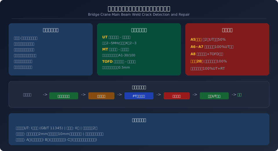
Field inspection data shows that main girder weld cracks are most frequently found in the following six high-risk areas:
Ends of flange-to-web welds — This is the most common crack location, accounting for approximately 35% of all weld cracks. Cracks propagate longitudinally along the weld and are particularly concentrated near the quarter-span points of the main girder, where shear forces are at their maximum.
Edges of coped holes at stiffener ends — When transverse stiffeners are welded to the web plate, a coped hole is left at the intersection of the stiffener bottom and the flange plate. The geometric discontinuity at the edge of these holes creates a stress concentration factor of 3 to 5 times, and cracks often propagate toward the web at a 45-degree angle.
Root of corbel-to-column welds — The corbel serves as the connection node between the main girder and the end carriage, carrying the full support reaction. The tensile zone at the weld root is prone to transverse cracking under alternating bending moments, which can be reliably identified using phased-array UT.
Detection Methods and Technical Parameters
Different crack locations and types require a combination of non-destructive testing methods. No single technique provides complete coverage — UT has low sensitivity to surface defects, MT can only detect surface and near-surface flaws, and RT is limited by radiation safety restrictions on site. Combining all three methods ensures comprehensive inspection coverage.
| Detection Method | Applicability Defect Type | Technical Parameters | Applicable Location | Detection Percentage |
|---|---|---|---|---|
| UTUltrasonic Testing (UT)Flaw detection | Internal Crack, Lack of Fusion, Incomplete Penetration | Frequency2~5MHz, Probe K2~3, DACCurve | Butt Weld, T-joint | A6~A7: 100% |
| MTMagnetic Particle Testing (MT) | Surface Crack, Near-Surface2mm Internal | Fluorescent Magnetic Particle, A1-30/100Test Piece | Fillet weld Surface, Run-off Tab | Critical Location100% |
| TOFDTime-of-Flight Diffraction (TOFD) | Crack Height Sizing, Depth Positioning | Frequency5~10MHz, Accuracy0.5mm | Thick Plate Butt Weld(8mmand Above) | Suspected Defect Supplementary |
| RTRadiographic Testing (RT) | Internal Defect Direct Radiographic Image | XRadiographic Testing (RT)/Gamma Source, IIGrade Acceptance | Manufacturing Stage Butt Weld | 10%Sampling Rate Above |
| PAUTPhased Array | Complex Geometry Weld Seam, Corbel Joint | 16~64Element, Sectorial Scan | Corbel Root, Variable Cross-Section | As Required |
Inspection Intervals and Acceptance Criteria
Inspection intervals for weld seams on bridge crane main girders are not fixed; they are dynamically adjusted based on work duty, service life, and operating environment. The Safety Technical Supervision Regulation for Lifting Appliances mandates differentiated non-destructive testing (NDT) frequencies for cranes of different work classifications. During the manufacturing stage, full penetration butt welds on the main girder must undergo 100% ultrasonic testing (UT) plus a minimum of 10% radiographic testing (RT) for cross-verification. For in-service inspections, the sampling ratio is determined by the crane's work duty.
Regarding acceptance criteria, cracks of any depth are considered non-conforming and cannot be accepted on the grounds that "minor cracks do not affect serviceability." Internal weld defects are evaluated by equivalent flaw size: a single defect with an equivalent size not exceeding 2mm and spaced more than 20mm from adjacent defects is acceptable; defects exceeding 3mm require rework. For near-surface flaws (within 2mm of the surface), magnetic particle testing (MT) is the preferred verification method to avoid blind spots inherent in UT.
Crack Repair Procedure and Verification
Once a weld crack is detected, the choice of repair procedure depends on the crack's depth, length, and location. Per the requirements of ISO 24817 — Specification for Repair of Steel Structures in Cranes, the repair process must follow a closed-loop sequence: "remove — verify — re-weld — re-inspect." Omitting any step can lead to repair failure or, worse, induce secondary cracking.
The core repair steps are as follows:
Step 1: Carbon Arc Gouging to Remove the Defect — Using a carbon electrode of 6–8mm diameter at a current of 250–350A, gouge progressively along the crack path. The gouge depth must extend at least 3mm beyond the crack tip, and the width should extend at least 20mm on each side of the crack. After gouging, grind the surface with an angle grinder to bare metal with a roughness (Ra) not exceeding 25 microns.
Step 2: Penetrant Testing (PT) to Confirm Complete Removal — Apply penetrant to the ground gouge surface (dwell time of at least 10 minutes). After development, verify that no crack indications remain. If any indication persists, return to Step 1 and repeat the gouging until PT passes completely. This step is the critical quality gate that prevents cracks from being "welded over."
Step 3: Re-Welding — Use filler metal matching the base material (Q355B base material with ER50-6 wire, 1.2mm diameter). Use CO₂ gas-shielded welding or mixed-gas-shielded welding with the following parameters: current 200–260A, voltage 24–28V, travel speed 250–350mm/min, and interpass temperature not exceeding 150°C. Use multi-pass welding, and peen each layer after deposition to relieve residual stress.
Step 4: Post-Weld UT Re-Inspection — After the weld cools to ambient temperature (allow 24 hours), perform 100% UT inspection to Grade I acceptance per the GB/T 11345 standard. If a defect is found again at the same location, one additional rework is permitted, but the total number of rework cycles must not exceed two. If a third repair is needed, the original design unit must be consulted; in severe cases, the entire weld section may need to be removed and re-fabricated.
Crack Prevention and Health Monitoring
The best strategy for managing weld cracks is "prevention over detection, and detection over repair." The following design-stage measures can significantly reduce the likelihood of weld cracking: use joint configurations with higher fatigue detail categories (e.g., full penetration welds instead of fillet welds), position welds away from high-stress zones in the structural design, relieve residual tensile stress through post-weld heat treatment or ultrasonic impact treatment, and grind the weld toe to a smooth transition radius (3mm or greater) to minimize stress concentration.
For bridge cranes already in service, maintaining a weld health record is an effective management practice. Each UT result is logged by weld number, tracking the trend of defect echo amplitude at the same weld location over time. If two consecutive inspections show that the equivalent flaw size at the same weld has grown by more than 50%, preventive rework should be scheduled even if the 3mm rework threshold has not been reached — this avoids the risk of sudden crack propagation between periodic inspections.
Weld Quality Acceptance Grade Comparison
| Weld Seam Type | Quality Grade | UTAcceptance Criteria | Surface Requirement | Rework Limitation |
|---|---|---|---|---|
| main girder flange plate-Web plate Butt Joint | IGrade | Single Defect Not Exceeding2mm | None Crack/Undercut Not Exceeding0.5mm | Not Exceeding2Times |
| Stiffener / Stiffening Rib Fillet weld | IIGrade | Single Defect Not Exceeding3mm | Leg Size Not Less Than Design Value | Not Exceeding2Times |
| Corbel Full Penetration Weld Seam | IGrade | 100%UT+10%RTComparison | Weld toe Grinding RNot Less Than3mm | Not Exceeding1Times |
| trolley rail Weld Seam | IIGrade | Sampling Not Less Than20% | No Surface Crack | Not Exceeding2Times |
| Non-Load-Bearing Weld Seam | IIIGrade | Visual inspection | No Visual Crack | No Limitation |
Frequently Asked Questions
Q: How often should non-destructive testing be performed on bridge crane main girder welds?
A: The testing frequency depends on the crane's work duty classification. For cranes rated A5 and below, ultrasonic testing (UT) must cover at least 50% of welds every two years. For classifications A6 through A7, 100% UT inspection of primary load-bearing welds is required annually. Heavy-duty cranes rated A8 require full inspection every six months, supplemented by TOFD for quantitative analysis. For cranes in service beyond 20 years, the structural inspection scope must be increased to 100% full coverage. Newly manufactured cranes undergo 100% UT on butt welds plus 10% RT comparative verification before leaving the factory.
Q: How is weld crack repair quality verified after rework?
A: After repair, the weld must cool to ambient temperature (at least 24 hours) before undergoing 100% UT inspection, with acceptance criteria per ISO 11666 Level 1 (equivalent to GB/T 11345). For full-penetration welds at critical nodes such as support brackets, an additional 10% RT radiographic comparison is required after UT. A follow-up inspection must be conducted within three months of repair to confirm no new cracks have initiated in the reworked area. The cumulative number of rework cycles at the same location must not exceed two; if more than two are needed, the original design engineer must evaluate whether the entire weld section should be removed and re-fabricated.
Q: What are the advantages of Magnetic Particle Testing (MT) versus Penetrant Testing (PT) for weld crack detection?
A: MT relies on the principle of magnetic flux leakage at surface defects in ferromagnetic materials, attracting magnetic particles to reveal surface-opening cracks and near-surface flaws up to 2 mm deep. It offers high sensitivity (A1-30/100 reference test pieces) and fast scanning speeds, making it ideal for large weld areas. PT works by capillary action drawing penetrant into surface-opening defects and is not limited by material magnetism, making it suitable for non-ferromagnetic materials such as stainless steel welds. PT provides direct visual indication of flaws and is well suited for localized verification after back-gouging of weld roots. The two methods are often used in combination: MT for initial broad-area screening, followed by PT for confirmation after defect removal.
Q: Is ultrasonic impact treatment effective in preventing weld cracks?
A: Ultrasonic impact treatment (UIT) applies high-frequency mechanical vibration to hammer the weld toe surface, introducing a compressive residual stress layer approximately 0.3–0.5 mm deep. This converts tensile residual stresses from welding into beneficial compressive stresses. Field data shows that UIT-treated welds can achieve a 3–8× improvement in fatigue life, with crack initiation delayed by 2–4×. The treated weld toe forms a smooth transition radius, reducing the stress concentration factor from 2.5–3.5 down to below 1.5. Kelude Heavy Industry currently applies UIT to all main girder welds on bridge cranes rated A6 and above before they leave the factory.
Kelude Heavy Industry is dedicated to research on metal structure safety technology for bridge cranes, providing industrial customers with end-to-end solutions from non-destructive weld testing to crack repair.
