

How to Calibrate a Bridge Crane Load Limiter
⚠️ Load Limiters are among the most critical safety protection devices on bridge cranes, and their calibration accuracy directly impacts lifting safety. Limiter setpoints are typically 90% of the rated lifting capacity (pre-warning) and 105% (trip action), with calibration error not exceeding ±1% of the rated load. Routine verification covers three core steps: zero calibration, span calibration, and operational reliability testing, with a calibration interval not exceeding 12 months.
Load limiters on bridge cranes — also referred to as overload limiters or load-limiting devices — are essential safety protection components that safeguard lifting operations. By continuously monitoring the lifting load, they trigger an audible and visual alarm or automatically cut hoisting power when the load exceeds preset thresholds, preventing serious incidents such as wire rope fracture, structural deformation, or even crane overturning caused by overloading. This article provides a systematic walkthrough of load limiter calibration procedures and key operational points.
How Load Limiters Work: Principles and Types
A load limiter consists of three main components: a sensor, a signal processing unit, and a display/control instrument. The sensor converts the lifting load into an electrical signal, which is amplified, converted from analog to digital, and then sent to a microprocessor for analysis and comparison. When the load reaches the preset pre-warning threshold (typically 90% of the rated lifting capacity), the controller triggers an audible and visual alarm. If the load continues to rise to the trip threshold (105% of rated lifting capacity), the controller outputs a cut-off signal, disconnecting power to the hoisting mechanism and applying braking.
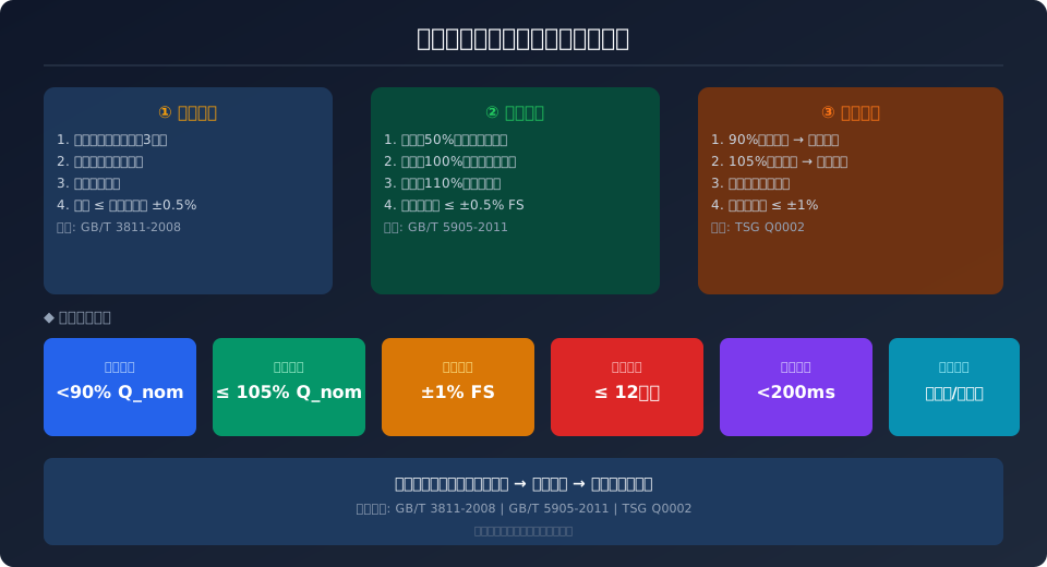
The diagram below illustrates the complete calibration workflow and key parameters for load limiters:
Load Limiter Calibration Workflow and Parameters1. PreparationVerify sensor modelPrepare standard weights / load cellLockout / tagout / verify zero energy2. Zero CalibrationNo-load conditionAdjust zero potentiometerDisplay reads zero ±0.5%3. Linearity CalibrationApply 50% rated loadAdjust gain / sensitivityError ≤±3%4. Threshold Testing90% pre-warning, no trip100–105% alarm and trip110% cut hoisting powerThreshold Setting Standards (per TSG Q0002 and GB/T 28264)<g transPre-Warning Threshold: 90% of Rated LoadAudible & Visual Pre-Warning, No Action Cut-offAlarm Threshold: 100~105%Audible & Visual Alarm, No Action Cut-offCut-off Threshold: 110% of Rated LoadImmediate Hoisting Power Cut-offRepeatability Error ≤ ±2%Max Deviation from 3 MeasurementsCalibration Cycle: Every 12 months under normal use | Immediate calibration after new installation / overhaul / sensor replacementSensor Type SelectionAxle Pin Type: Accuracy ±1%, suitable for new installations / retrofitsSide-Pressure Type: Accuracy ±3%, easy installation, suitable for retrofitting existing cranesCalibration Equipment RequirementsStandard Test Weights: Accuracy class M1 or higher, total weight ≥ rated loadStandard Load Cell: Accuracy class 0.5, measuring range ≥ 1.2 x rated load
Based on the sensor type, the two most common configurations are the side-pressure type and the bearing housing type. The side-pressure sensor is mounted on the fixed end of the hoisting wire rope and indirectly derives the load value by measuring the rope tension. The bearing housing sensor, installed beneath the bearing housing of the upper pulley block, directly measures the support reaction force. This provides higher accuracy and better immunity to interference, making it ideal for heavy-capacity cranes and frequent-duty applications. For cranes equipped with variable-frequency speed control, an electronic load limiting function can be implemented using the torque output signal from the frequency inverter (VFD). However, it is important to note that an electronic limiter cannot fully replace an independent mechanical limiter.
Pre-Calibration Preparation Checklist
Before starting the calibration, the following preparation steps are essential to ensure both accuracy and safety. First, verify that all crane mechanisms operate smoothly, the brake is reliable, and the hoisting wire rope is neatly spooled without broken wires or deformation. Next, the standard test weights or load used for calibration must be certified by metrological verification, with an accuracy of no less than ±0.5%, and accompanied by a valid calibration certificate. The calibration site must be clearly marked as a safety zone with warning signs, and unauthorized personnel must be kept out from under the suspended load. The technician performing the calibration must hold a valid crane operator certificate (Q2) and be thoroughly familiar with the limiter's technical parameters and operational procedures.
For tooling, you will need a calibrated digital multimeter (accuracy class 0.5), an insulation resistance tester (500V range), and a signal generator (for simulating signals during electronic limiter calibration). For digital limiters communicating via CAN Bus or RS485, the corresponding communication software and interface converter are also required. All measuring instruments must be within their valid calibration period. Before beginning, review the equipment's maintenance records to understand previous calibration data and any noted deviations.
Step-by-Step Zero and Linearity Calibration
Step 1: Power-On Preheating & Initial Inspection — Power up the limiter and allow it to preheat for at least 3 minutes. Confirm that all display functions work correctly and the digital readout is clear without any missing segments. Inspect the sensor connecting cable for damage, ensure all joints are tight, and verify that the shield grounding is secure. For limiters that have been out of service for an extended period, perform an insulation resistance test; the insulation resistance from the sensor to ground should be no less than 2MΩ.
Step 2: Zero Calibration — With the crane completely unloaded (hook block without any load), adjust the limiter display to zero. If the deviation exceeds ±0.5% of the rated load, first check for loose sensor mounting or any external strain on the signal cable. If these are correct, use the instrument's zero adjustment function to calibrate. For bearing housing sensors, check that the support reaction force is evenly distributed across all sensors, adjusting the shim height of the bearing housing if necessary.
Step 3: 50% Measuring Range Calibration — Apply a standard test weight equal to 50% of the rated lifting capacity. Hoist the hook to approximately 200mm above the ground and let it settle. Read the display value; the error should not exceed ±0.5% of the rated load. If out of tolerance, adjust the instrument's gain potentiometer or modify the corresponding calibration parameter until the reading is within specification.
Step 4: 100% Measuring Range Calibration — Apply a standard test weight equal to 100% of the rated lifting capacity. Hoist to 200mm above the ground and let it settle. Read the display value. Across the full measuring range, the linearity error of the limiter should not exceed ±0.5% FS (Full Scale). If the linearity error is significant, check the sensor's linearity and repeatability; replace the sensor if it does not meet requirements.
Action Threshold Testing Procedure
Step 5: Pre-Warning Function Test — Apply a load equal to 90% of the rated lifting capacity and hoist slowly. When the load reaches the pre-warning threshold, the limiter should trigger an audible and visual alarm (buzzer sounding, red warning light flashing) without cutting off the hoisting power supply. The alarm should persist until the load drops below the threshold and the operator manually resets the system.
Step 6: Action Cut-off Test — Continue increasing the load to 105% of the rated lifting capacity. The limiter must reliably cut off the hoisting mechanism's power supply within the specified time (typically less than 200ms) and simultaneously energize the brake for braking. After the cut-off, the hoisting mechanism should only be able to move in the lowering direction, not hoisting. Repeat this test 3 times; each test must result in a reliable action. Note: For limiters with an overload time-delay protection feature, perform the test according to the product manual's instructions to ensure the delay setting is appropriate.
Step 7: Repeatability Verification — Repeat the test at least 3 times at both the 90% and 105% action points, recording the actual load value at which the action occurs each time. The repeatability error (the difference between the maximum and minimum values divided by the rated load) should not exceed ±1%. If repeatability is poor, potential causes include loose sensor mounting, poor contact in the signal cable, or drift in the instrument's internal A/D converter.
Calibration Parameter Reference Table
| Inspection Items | Technical Requirements | Acceptance Criteria Standard |
|---|---|---|
| Zero Drift | No-Load Preheating3Re-zeroing after Minutes | Deviation Shall Not Exceedrated loadof&#x B1;0.5% |
| Measuring Range Linearity | 50%and100%Point Calibration | Error Shall Not Exceed&#x B1;0.5% FS |
| Pre-Alarm Setpoint | Set to90%Rated Lifting Capacity | Actuation Deviation Shall Not Exceed&#x B1;5% |
| Cut-Off Setpoint | Set to105%Rated Lifting Capacity | Actuation Deviation Shall Not Exceed&#x B1;5% |
| Repeatability Error | Repeat at Each Actuation Point Testing Not Less Than3Cycles | Shall Not Exceedrated loadof&#x B1;1% |
| Cut-Off Response time | After Overloadlimiter Cut-Off Power Supply | Shall Not Exceed200ms |
| Calibration Interval | Under Normal Operating Conditions | Shall Not Exceed12Months |
Safety Precautions for Load Limiters
🚫 Never bypass or disable the limiter — Some operators, for the sake of convenience, short-circuit the limiter output contacts or unplug its power supply. This is extremely dangerous. A disabled limiter means the crane loses its last line of defense against overload. Overloading can directly jeopardize the safety of the wire rope, brake, and steel structure, potentially leading to a major accident. Under no circumstances should the limiter's protective function be compromised.
⚠️ Calibration loads must be securely positioned — Calibration test weights or loads should be evenly distributed and firmly secured beneath the lifting spreader. The safety factor for connecting components and rigging must not be less than 6. The mass deviation of individual test weights should not exceed ±0.5% of the marked value. No personnel are allowed to stand or pass beneath the load during calibration. After calibration, remove and store the test weights promptly to avoid unnecessary static load stress on the crane's steel structure.
✅ Maintain written records after each calibration — After each calibration, the technician must complete a Load Limiter Calibration Record, including: calibration date, limiter model and serial number, total test weight and accuracy grade, displayed vs. standard values at each calibration point, actual load values at which pre-warning and cut-off actions occurred, calibration conclusion, and the technician's signature. The record must be filed in the crane's safety technical archive and retained for at least 3 years. If a limiter fails calibration, notify the maintenance department immediately for repair or replacement. The limiter may only be returned to service after passing a re-calibration.
Load Limiter FAQs
Q: How often should a lifting capacity limiter be calibrated, and what are the risks of exceeding the interval?
A: According to TSG Q0002 Safety Technical Supervision Regulation for Lifting Appliances, the calibration interval for lifting capacity limiters must not exceed 12 months. For cranes classified under A6~A8 heavy-duty work duty, it is recommended to shorten the interval to 6 months. If the calibration interval is exceeded, the sensor may suffer from zero drift and sensitivity degradation, causing the actual trip threshold to deviate significantly from the set value. In extreme cases, the limiter may fail to activate during an overload, completely losing its protective function.
Q: How do I choose between a side-pressure sensor and a bearing housing sensor?
A: The side-pressure sensor is easy to install and cost-effective, making it suitable for small and medium bridge cranes with a lifting capacity up to 20 t. However, its measurement accuracy is affected by the wire rope's bending radius and friction, which can lead to a deviation of 3%–5% over time. The bearing housing sensor directly measures the reaction force of the pulley block, offering high accuracy (±0.5% FS) and excellent long-term stability. It is ideal for heavy-duty applications (20 t and above) and environments such as metallurgy and foundries where precise load monitoring is critical. The choice should consider lifting capacity, work duty, cost-effectiveness, and ease of maintenance.
Q: How can a lifting capacity limiter be calibrated on-site without standard test weights?
A: When standard test weights are unavailable, the substitution method can be used. This involves using a calibrated electronic crane scale as a reference standard, connected in series between the hook and the load. The scale's reading serves as the actual load value for calibrating the limiter. The accuracy of this method depends on the scale's accuracy grade — use a scale with at least Class III accuracy (error not exceeding ±0.1% FS) that is within its calibration validity period. Alternatively, a sensor simulator (signal generator) can perform an electrical signal simulation on electronic limiters. However, simulation cannot fully replace physical load testing, so a real-load verification should be performed at least once a year.
Q: What is the difference between electronic and mechanical limiters? Can they replace each other?
A: Electronic limiters calculate the load using the VFD's torque output signal or a dedicated load cell. They offer fast response (less than 50 ms) and feature data logging and communication capabilities, representing the trend toward smart cranes. Mechanical limiters detect overload directly through eccentric wheels, levers, or spring mechanisms and mechanically interrupt the control circuit. They are simple in construction, independent of the power supply, and highly reliable. According to GB/T 28264-2012 Safety Monitoring and Management System for Lifting Appliances, cranes equipped with electronic limiters should also retain an independent mechanical overload protection device as a redundancy backup. The two types cannot fully replace each other.
