

Crane Buffer Types: Polyurethane vs Spring vs Hydraulic
📋 At a Glance
Crane buffer selection comes down to four key factors: impact speed, buffer capacity, work duty, and mounting space. Polyurethane buffers are the low-cost choice for small-to-mid-size cranes (≤1.0 m/s); spring buffers offer simple maintenance for mid-to-large equipment (≤1.5 m/s); hydraulic buffers deliver the highest energy absorption for high-speed, heavy-load applications (≤4.0 m/s); and rubber buffers suit light-duty, compact cranes (≤0.8 m/s). Kelude offers a full range of custom buffer solutions — contact our engineers for an impact energy calculation report.
Crane Buffer Function & Selection: What Are the Key Criteria?
Crane buffers are safety devices mounted at the ends of the travel mechanism or at the ends of the crane rail. Their job is to absorb impact energy when the crane or trolley reaches its limit position, preventing rigid collisions that could deform the steel structure, damage the travel mechanism, or injure personnel. Per Section 5.8 of the ISO 4301 Crane Design Standard, all bridge and gantry cranes must be equipped with buffers on their travel mechanisms, and the buffer capacity must meet the impact energy requirements at rated speed.
Buffer selection follows a four-step decision process:
Step 1: Determine the impact mass. Use the total crane mass — with rated load for full-load conditions, or the trolley/whole-crane mass for no-load conditions. This is the baseline for calculating impact kinetic energy.
Step 2: Determine the impact speed. Take 70%–100% of the rated travel speed (ISO 4301 specifies 85% of rated speed for elastic buffers and 100% for hydraulic buffers), then factor in wind load effects.
Step 3: Calculate impact kinetic energy. Ek = 0.5 × m × v², where m is the impact mass (kg) and v is the impact speed (m/s). The selected buffer capacity must be at least 1.25 times the calculated kinetic energy to ensure an adequate safety factor.
Step 4: Match the buffer type. Choose from polyurethane, spring, hydraulic, or rubber based on mounting space, working environment temperature, maintenance intervals, and budget. Kelude recommends a polyurethane-plus-spring combination for most applications, balancing energy absorption efficiency with service life.
Beyond the ISO 4301 design standard, buffer selection should also reference GB/T 16564 (Crane Buffers — Terminology) for technical parameter definitions and GB/T 20305 (Crane Buffers) for product classification and acceptance requirements. For European markets, FEM 9.882 provides a complete methodology for buffer design calculations and serves as a useful supplement for heavy-duty crane selection.
Polyurethane vs. Spring Buffers: Technical Specs & Best-Fit Applications
Polyurethane and spring buffers are the two most widely used buffer types on bridge cranes, but they differ significantly in buffering mechanism, energy absorption efficiency, suitable applications, and lifecycle cost. Here's a side-by-side comparison across six key dimensions:
| Comparison Parameter | Polyurethane buffer | Spring buffer |
|---|---|---|
| Buffer Mechanism | Elasticity Volumetric Compression Deformation Energy Absorption | Spiral Spring Elasticity Energy Storage |
| Maximum Impact Speed | ≤ 1.0 m/s | ≤ 1.5 m/s |
| Energy Absorption Rate | ≥ 40% | ≥ 50% |
| Applicable Temperature Range | -20°C ~ +60°C | -40°C ~ +80°C |
| Reference Service Life | 500,000 Impact Cycles | 1,000,000 Impact Cycles |
| Applicable Tonnage Range | ≤ 50tBridge Crane / Overhead Crane | 10t ~ 300tVarious Typescrane |
Polyurethane buffers offer a standout advantage in initial cost—roughly 40% to 60% of a comparable spring buffer—and require no lubrication maintenance. However, their elasticity degrades noticeably in low-temperature environments. Kelude prioritizes polyurethane buffers as standard on small- and medium-capacity bridge cranes (≤20t), backed by lab testing that shows residual deformation of ≤3% after 500,000 impact cycles.
Spring buffers are prized for their simple maintenance and excellent temperature adaptability—when a spring fails, only the spring component needs replacing, not the entire buffer housing. The trade-off is rebound: after impact, the stored spring energy releases as a reverse thrust that can push the crane backward. The ISO 4301 Crane Design Standard requires that spring buffer selection account for rebound displacement and reserve reverse-travel clearance.
Hydraulic vs. Rubber Buffers: Energy Absorption & Inspection Standards Compared
Hydraulic buffers operate on a throttling-damping principle: hydraulic oil forced through an orifice generates damping force that absorbs kinetic energy, delivering the highest energy-absorption efficiency with no reaction force. Rubber buffers, by contrast, rely on internal friction (hysteresis loss) within the rubber material to absorb energy—simple in construction but comparatively less efficient. The table below compares them from the standpoint of inspection standards and technical requirements:
| Inspection Item | Hydraulic buffer Requirements | Rubber buffer Requirements |
|---|---|---|
| Basis Standard | GB/T 20305 Appendix A | GB/T 20305 Appendix B |
| Rated Stroke Deviation | ±2% Rated Stroke | ±5% Rated Stroke |
| Maximumbuffer force Deviation | ≤ ±10% Rated Force | ≤ ±15% Rated Force |
| Sealing Performance Test | 1.5Hold at Multiples of Rated Pressure5min No Leakage | Not Applicable |
| Durability test | Rated Operating Conditions100,000 Cycles Without Functional Failure | Rated Operating Conditions50,000 Cycles Without Cracking or Craze |
| Application Scenarios | Metallurgy/Port Large-Scalecrane | Small-Scale Hoist/jib crane Terminal |
Hydraulic buffers require attention to three key maintenance points during service:
① Check the oil level quarterly. When the hydraulic oil level drops below the lower mark on the dipstick, replenish with L-HM46 anti-wear hydraulic oil.
② Replace a damaged piston rod dust cover within 48 hours to prevent dust from entering the seal cavity and causing scoring on the piston rod.
③ Perform a static pressure-holding test annually. The buffer must maintain a stroke retraction of ≤2mm for 5 minutes under 1.25 times the rated load.
Kelude Heavy Industry offers a 3-year warranty on hydraulic buffers, with free replacement of seal components during the warranty period.
When selecting rubber buffers, the compression set rate is a critical parameter to verify. Per Appendix B of GB/T 20305, the compression set of rubber buffers must not exceed 25% after 70°C × 24h hot-air aging; exceeding this value indicates failure and requires replacement. For outdoor cranes, ozone-resistant rubber compounds (EPDM or CR neoprene) are mandatory. Standard NR natural rubber buffers lose more than 50% of their service life under outdoor UV exposure.
6 Crane Buffer Types: Side-by-Side Specification Comparison
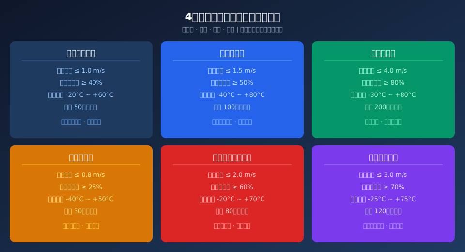
The core parameters of six buffer types—polyurethane, spring, hydraulic, rubber, polyurethane foam, and elastomer—are organized into data cards for quick reference during selection:
Polyurethane Buffer
Impact speed ≤ 1.0m/s
Energy absorption ≥ 40%
Temperature -20°C~+60°C
Service life 500,000 cycles
Lowest cost · Ideal for small to medium cranes
Spring Buffer
Impact speed ≤ 1.5m/s
Energy absorption ≥ 50%
Temperature -40°C~+80°C
Service life 1,000,000 cycles
Simple maintenance · Wide temperature range
Hydraulic Buffer
Impact speed ≤ 4.0m/s
Energy absorption ≥ 80%
Temperature -30°C~+80°C
Service life 2,000,000 cycles
High-speed heavy loads · No rebound force
Rubber Buffer
Impact speed ≤ 0.8m/s
Energy absorption ≥ 25%
Temperature -40°C~+50°C
Service life 300,000 cycles
Simple construction · Light-duty equipment
Polyurethane Foam Buffer
Impact speed ≤ 2.0m/s
Energy absorption ≥ 60%
Temperature -20°C~+70°C
Service life 800,000 cycles
High energy density · Excellent rebound
Elastomer Buffer
Impact speed ≤ 3.0m/s
Energy absorption ≥ 70%
Temperature -25°C~+75°C
Service life 1,200,000 cycles
Custom capacity · Proprietary formulation
Crane Buffer Selection: 3-Step Impact Energy Calculation
In practical engineering, buffer specifications must be determined based on impact energy calculations. The complete three-step process is as follows:
Step 1: Determine the effective impact mass — For bridge crane bridge buffers, use the total crane mass (fully loaded when rated load is included; for no-load conditions, use trolley mass + crane bridge mass). For gantry cranes, add the equivalent wind load mass (calculated as Fw = 1.2 × q × A, where q is the wind pressure taken as 250N/m² and A is the windward area).
Step 2: Determine the design impact speed — The rated impact speed of the buffer is taken as 85% of the crane's rated travel speed (for polyurethane/spring/rubber types) or 100% (for hydraulic types), converted to m/s. For example, if the travel speed is 20m/min, then v = 20 ÷ 60 × 0.85 = 0.283 m/s.
Step 3: Calculate the required buffer capacity — The rated buffer capacity W(kJ) = 0.5 × m(kg) × v²(m/s) ÷ 1000 × K, where K is the safety factor taken as 1.25. Select a buffer with a rated capacity equal to or greater than the calculated value—never downsize. The Kelude Heavy Industry engineering team provides free buffer selection calculation reports, including impact energy verification and installation position recommendations.
📖 Related Reading
Below are previously published articles by Kelude Heavy Industry on crane core component selection and standard interpretation:
• FEM 1.001 Crane Test Specification: 3 Load Test Procedures & 6 Acceptance Criteria
• Troubleshooting Crane Load Slipping: 6 Braking System Causes & Drop Distance Acceptance Standards
• Crane Brake Installation & Adjustment: 6 Clearance Parameter Standards & Braking Torque Calibration
5 Common Crane Buffer Selection Problems and Solutions
Q: Is there a significant difference between polyurethane buffers and spring buffers in real-world applications?
A: The core differences come down to three factors: ① Energy absorption mechanism — polyurethane dissipates energy through internal material friction and heat generation (no rebound), while springs store energy elastically (producing rebound force); ② Temperature adaptability — polyurethane hardness rises sharply below -20°C, reducing absorption efficiency to below 25%, whereas springs operate normally across -40°C to +80°C; ③ Maintenance intervals — polyurethane buffers are maintenance-free but must be replaced as a complete unit once cracks appear, while spring buffers allow individual replacement of failed spring coils, with per-unit maintenance costs roughly 60% lower. Kelude Heavy Industry recommends spring buffers for cranes rated M5 and above, and polyurethane buffers for M3 to M4 duty classifications.
Q: What mandatory factory inspection requirements does GB/T 20305 impose on crane buffers?
A: Chapter 7 of GB/T 20305 Crane Buffers specifies three mandatory factory acceptance tests: ① Visual and dimensional inspection — buffer housing must be free of cracks, sand holes, and porosity, with mounting dimension deviation ≤ ±2 mm; ② Buffer force characteristic test — measured maximum buffer force at rated stroke must deviate no more than ±15% from the nameplate value (±10% for hydraulic types); ③ Compression set test — polyurethane/rubber buffers must show permanent deformation ≤ 25% after aging at 70°C for 24 hours, while spring buffers must maintain free height variation ≤ 2% after 100 full-load compression cycles. Failure of any single test results in rejection of the entire batch. All Kelude buffers ship with a third-party inspection report.
Q: What should I do when a crane buffer makes abnormal noise or cracks and detaches?
A: Abnormal noise or fragmentation typically points to one of three failure modes: ① Surface crazing or fracture on a polyurethane buffer — indicates fatigue aging or impact overload; shut down immediately, replace the buffer, and re-verify impact energy. If actual travel speed exceeds 85% of the rated value, install a deceleration limit switch. ② Metallic clanging from a spring buffer — check the clearance between the spring seat and guide sleeve (standard ≤ 1.5 mm); replace the guide sleeve if clearance is excessive, and inspect the buffer base weld seam for cracks. ③ A hissing air-leak sound from a hydraulic buffer — indicates seal ring failure causing nitrogen leakage; disassemble, replace the complete seal kit, and recharge nitrogen to the nameplate pre-charge pressure (typically 2–4 MPa). Kelude Heavy Industry offers a 48-hour on-site buffer diagnostic service.
Q: How much does a set of crane buffers cost for different tonnages, and how should they be configured?
A: Buffer pricing varies by type and energy-absorption capacity: polyurethane buffers (1–20 kJ capacity) range from $30 to $120 per unit; spring buffers (5–100 kJ) from $90 to $445 per unit; hydraulic buffers (20–500 kJ) from $300 to $2,965 per unit. Tonnage matching recommendations: cranes ≤ 10 t — fit four polyurethane buffers (capacity ≥ 5 kJ each); 10 t to 50 t — fit four spring buffers (capacity ≥ 20 kJ each); metallurgical/ladle cranes ≥ 50 t — fit four hydraulic buffers on the crane bridge (capacity ≥ 100 kJ each) and two spring buffers on the trolley. Kelude Heavy Industry provides free buffer sizing calculations — send us your crane parameters and we'll return a configuration list with quotation.
This article was compiled and published by the Kelude Heavy Industry technical department. Buffer selection parameters are based on current standards including ISO 4301 Crane Design Standard, GB/T 20305, and FEM 9.882. To request a model-specific buffer sizing calculation sheet or product catalog, contact a Kelude Heavy Industry applications engineer for a customized solution.
