

Crane Wire Rope: Fiber Core vs Steel Core & Rotation-Resistant
📋 Summary
Selecting the right crane wire rope requires careful evaluation of construction type (fiber core FC, independent wire rope core IWRC, rotation-resistant), nominal diameter and its matching ratio with drum and sheave diameters (D/d), minimum breaking force and safety factor verification, as well as discard criteria (number of broken wires, diameter reduction, corrosion, deformation, wear). This article compares the core parameters of four wire rope constructions and outlines the five discard criteria per ISO 4309:2017 and GB/T 5972-2016, helping engineers make informed decisions from selection through maintenance.
The wire rope is the most critical load-bearing component in a crane's hoisting mechanism. Correct selection directly impacts equipment safety and service life. Per the requirements of ISO 4301 Crane Design Standard, the minimum breaking force of the wire rope must satisfy the safety factor condition F₀ ≥ S × n, where S is the maximum static working load on the rope and n is the safety factor, which varies with the mechanism's work duty classification. Additionally, ISO 4308-1:2003 Cranes — Selection of wire ropes specifies that rope selection must account for sheave and drum diameters, rope construction, and expected service life, providing engineers with a complete selection framework.
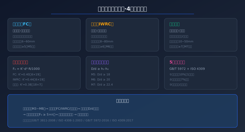
4 Wire Rope Constructions and Their Best-Fit Applications
Wire ropes used in cranes are generally classified into four construction types: point contact, line contact, full-lock (surface contact), and compacted strand. Point-contact ropes (e.g., 6×19) are simple to manufacture but experience high contact stress between inner and outer wires, making them suitable for standard hoisting applications. Line-contact ropes (e.g., 6×19W, 6×25Fi) reduce contact stress through parallel laying of wires in different layers, achieving roughly 30% longer fatigue life than point-contact designs — they are the standard configuration for Kelude's bridge crane hoisting mechanisms.
Full-lock (surface contact) ropes use shaped outer wires that are die-drawn to create a smooth surface contact area, delivering excellent wear resistance for multi-layer winding applications. Compacted strand ropes undergo forging or rolling to plastically deform the strand wires, achieving a metal fill factor above 0.85; at the same diameter, their breaking force is 15%–20% higher than that of ordinary wire ropes. When selecting, the rope lay construction should be matched to the work duty class: single-layer strand is acceptable for M3 and below, while line-contact or multi-strand constructions are recommended for M4 and above.
Fiber Core vs. Steel Core: 4 Key Parameter Comparison
Wire rope cores fall into two main categories: fiber core (FC) and independent wire rope core (IWRC). The two differ significantly in flexibility, crush resistance, metallic cross-sectional area, and operating temperature range. Fiber cores, made from natural sisal or synthetic polypropylene, offer excellent oil retention and lubrication, allowing the rope to self-lubricate continuously during operation and delaying internal wire corrosion. They provide good flexibility and are well suited for single-layer winding and applications requiring frequent bending.
Steel cores (IWRC) use an independent wire rope as the core, delivering far higher crush resistance than fiber cores. They resist deformation from outer wire pressure during multi-layer winding and provide a larger metallic cross-sectional area — at the same nominal diameter, the minimum breaking force is approximately 8%–12% higher than FC ropes. For Kelude's metallurgical and foundry cranes operating in high-temperature environments, IWRC steel-core ropes are mandatory: fiber cores carbonize and fail at ambient temperatures above 60°C. IWRC ropes also exhibit lower structural elongation, making them ideal for precision lifting applications that require accurate positioning.
Rotation-Resistant Wire Rope: 3 Selection Essentials
Rotation-resistant wire rope (also called non-rotating rope) uses opposing lay directions between inner and outer strand layers so that the rotational torque generated under load cancels out. This construction is particularly suited for single-fall hoisting and high-lift cranes, preventing load spin caused by hook rotation. Three key points must be considered when selecting rotation-resistant rope.
First, rotation-resistant ropes typically come in three common constructions: 18×7, 19×7, and 35×7. The 18×7 construction has 12 outer strands laid right regular and 6 inner strands laid left regular, balancing torque between layers — suitable for lift heights up to 100 m. The 35×7 construction, with more strands and a higher metal fill factor, is designed for ultra-high lift applications above 150 m, such as the hoisting mechanism of Kelude's hydropower station gantry cranes.
Second, rotation-resistant ropes require stricter D/d drum and sheave diameter ratios: D/d ≥ 22.4 for duty class M4, D/d ≥ 25 for M5, and D/d ≥ 28 for M6 — all higher than the ratios required for standard ropes of the same class. This is because the multi-strand construction is prone to "birdcaging" when bent around excessively small radii.
Third, rope end termination must include reliable anti-rotation measures. Never weld the end of a rotation-resistant rope directly. Use wedge sockets or alloy-poured thimbles instead, and install an anti-rotation device below the termination to prevent accumulated twist from loosening the strands during lifting operations.
Wire Rope Diameter Matching: Drum-to-Rope Ratio and Safety Factor
Per ISO 4301 Crane Design Standard and ISO 4308-1:2003, the ratio of drum and sheave pitch diameters (D) to the rope's nominal diameter (d) — the D/d ratio — is the core parameter governing rope service life. An excessively low D/d ratio causes high bending stress and a sharp drop in fatigue life. The minimum D/d values corresponding to standard mechanism duty classifications are: M1 ≥ 14, M2 ≥ 16, M3 ≥ 18, M4 ≥ 20, M5 ≥ 22.4, and M6 ≥ 25.
The safety factor n also varies with duty classification: M1 n ≥ 4.0, M2 n ≥ 4.5, M3 n ≥ 5.0, M4 n ≥ 6.0, M5 n ≥ 7.0, and M6 n ≥ 9.0. Kelude performs an actual breaking force verification on every crane's wire rope during the factory acceptance test, ensuring the measured F₀ value meets a margin of S × n × 1.15. Selection calculations should also account for the drum groove angle, fleet angle, and the rope's entry angle onto the drum; a fleet angle exceeding 4° requires the installation of a rope guide.
5 Discard Criteria and Routine Inspection Intervals
According to GB/T 5972-2016 — Cranes: Wire rope maintenance, inspection and discard and ISO 4309:2017 Wire Rope Inspection Standard, a wire rope must be discarded when any one of the following five conditions is met: ① the number of visible broken wires within one rope lay length reaches 10% of the total wire count; ② the rope diameter is reduced by more than 7% relative to its nominal diameter; ③ an entire strand breaks or the rope core becomes exposed; ④ visible corrosion pitting or surface rust has reduced the rope diameter; ⑤ the rope shows permanent deformation such as cage distortion, strand protrusion, kinking, or flattening.
Routine inspection intervals are divided into three tiers based on equipment usage frequency: cranes in continuous service (more than 4,000 operating hours per year) require a visual inspection weekly and a detailed inspection monthly; cranes in intermittent service (2,000–4,000 hours per year) require visual inspection every two weeks and a detailed inspection every two months; cranes in occasional service (fewer than 2,000 hours per year) require monthly visual inspection and a detailed inspection every six months. Detailed inspections cover lubrication condition, security of rope end terminations, wear on drum grooves, and load distribution uniformity at the equalizer sheave.
Wire Rope Construction Parameter Comparison Table
| Wire Rope Type | Core Construction | Nominal Diameter Range | Application Work Duty / Classification | Safety factor Requirement | Recommendedminimum D/d |
|---|---|---|---|---|---|
| 6×19+FCFiber core | Natural Fiber/Synthetic Fiber | 6~40mm | M3~M5 | 4.0~5.0 | 18 |
| 6×25Fi+IWRCSteel Core | independent wire rope Steel Core | 8~60mm | M5~M7 | 5.0~7.0 | 20 |
| 18×7 Resistance Rotation Type | Steel Core IWRC | 10~50mm | M5~M7(Single Rope) | 5.0~7.0 | 22.4 |
| 35×7 Resistance Rotation Type | Steel Core IWRC | 14~64mm | M6~M8 | 6.0~9.0 | 25 |
| Compacted strand+IWRC | independent wire rope Steel Core | 12~80mm | M6~M8 | 6.0~9.0 | 20 |
| Surface Contact Sealing Wire Rope | Steel Core IWRC | 16~100mm | M7~M8 | 7.0~9.0 | 25 |
Scrap Criteria vs. Inspection Methods: A Side-by-Side Comparison
| Discard Criteria | Judgment Standard | Inspection Method | Detection Tool | Reference Clause | Inspection Frequency |
|---|---|---|---|---|---|
| Number of broken wires | 1Wire Breaks Within One Lay Length>10% | Visual+Counting | optical flat | GB/T 5972 6.2.2 | Weekly~Monthly |
| Diameter reduction | Diameter reduction>7%Nominal | Wide Mouthoptical flat Measurement | Wide-Jaw Caliper | ISO 4309 Wire Rope Inspection Standard 5.3 | Monthly |
| Corrosion/Corrosion | Surface Pitting or Internal Corrosion | Visual+Flaw detection | Wire Ropeflaw detector | GB/T 5972 6.2.4 | Monthly~Quarterly |
| Deformation(Cage/Kink) | Permanent Deformation | Visual Inspection | Tape Measure/Straight Edge | ISO 4309 Wire Rope Inspection Standard 5.5.2 | Weekly |
| Strand breakage/Extrusion | Strand Extrusion or Core Exposure | Visual Inspection | Naked Eye/Magnifying Glass | GB/T 5972 6.2.5 | Weekly~Monthly |
| Lubrication Loss | Dry Rope Surface, Absence of Oil Film | Touch+Visual | Wiping with Fiber Cloth | ISO 4309 Wire Rope Inspection Standard 4.3.2 | Monthly |
Minimum Breaking Force
F₀≥S×n
M5: n≥5 / M6: n≥6
Drum-to-Rope Diameter Ratio
D/d≥18~25
Increases with M3 through M8
Discard Limit — Broken Wires
≤10% per rope lay
ISO 4309 Wire Rope Inspection Standard, Clause 6.2.2
Diameter Reduction Threshold
≤7% of nominal diameter
ISO 4309, Clause 5.3
IWRC Strength Advantage
+8%~12%
vs. fiber-core (FC) construction
Fiber Core Temperature Limit
≤60℃
Switch to IWRC above this threshold
📖 Further Reading
ISO 4301 Crane Design Standard — Selection method covering 9 load combinations and work duty classifications A1 to A8
ISO 16625 — Wire Rope Drum and Sheave Selection & Maintenance Guide
Frequently Asked Questions
Q: How do I choose between fiber-core and steel-core wire rope for a hoisting mechanism?
A: Fiber-core (FC) rope suits single-layer winding applications, ambient temperatures up to 60°C, and lighter-duty cranes in classifications M3 to M5 where multi-layer spooling is not required. It offers good flexibility and self-lubricating properties. Steel-core (IWRC) rope is the right choice for multi-layer winding, high-temperature environments above 60°C, and medium-to-heavy cranes in classifications M5 to M7. IWRC provides over 30% higher crush resistance than FC, delivers 8%–12% greater breaking force at the same diameter, and is the standard specification on Kelude metallurgical and ladle cranes.
Q: What are the specific discard criteria for broken wires under ISO 4309?
A: Clause 6.2.2 of ISO 4309 states that a wire rope must be removed from service immediately when the number of visible broken outer wires within one rope lay reaches 10% of the total number of wires in the rope. For a 6×19+FC construction (114 outer wires), 12 broken wires within a single lay triggers discard. For a 6×25Fi+IWRC construction, the discard threshold is 14 broken wires within one lay. Additionally, if broken wires are concentrated in a single strand or clustered around the rope end fixing joint, replacement should be evaluated even if the 10% threshold has not been reached.
Q: Can a crane wire rope with birdcage deformation still be used?
A: No, it must not be used. Per Clause 5.5.2 of ISO 4309:2017, any permanent deformation such as cage distortion (birdcaging), strand protrusion, kinking, flattening, or bending requires immediate removal from service and replacement. Birdcage deformation is commonly seen in rotation-resistant wire ropes and is typically caused by an insufficient D/d ratio, excessive fleet angle, or impact load. Kelude recommends that upon detecting birdcage deformation, in addition to replacing the wire rope, you should also verify that drum groove wear and pulley fleet angles remain within allowable limits.
Q: How many years of service before a crane wire rope must be replaced?
A: The service life of a wire rope depends on its work duty and operating conditions — there is no fixed calendar-based rule. For light-duty cranes in Work Duty M3~M4, wire ropes typically last 3–5 years or 8,000–12,000 accumulated operating hours under normal use and maintenance. For medium-duty cranes in Work Duty M5~M6, the expected service life is generally 2–3 years or 5,000–8,000 hours. For heavy-duty or metallurgical cranes in Work Duty M7~M8, wire rope life is usually 1–2 years, and in high-temperature or dusty environments, replacement may be needed every 6–12 months. The final decision must always be based on the five discard criteria in ISO 4309, not simply on elapsed time.
