

How to Adjust Crane Brakes: 6 Gap Parameters & Torque Calibration
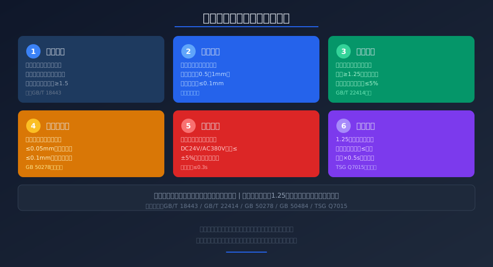
Summary: The crane brake is a critical component for hoisting safety, and installation & commissioning must strictly follow six key technical parameters. This article provides a systematic walkthrough of the full process—brake shoe gap adjustment (standard 0.5 to 1 mm), braking torque calibration (no load slip beyond 1.25 times rated load), coaxiality alignment (≤0.05 mm), electrical parameter verification (voltage deviation ≤±5%), and dynamic load stop tests at 1.25 times rated load—offering field installers a practical, standardized work procedure.
The quality of crane brake installation and commissioning directly determines operational safety. Per ISO 4301-1, "Cranes—Hoisting mechanism braking systems—Technical conditions", the brake must reliably stop the load at 1.25 times the rated load, with a braking distance not exceeding the lifting speed multiplied by 0.5 seconds. Additionally, ISO 4306-1, "Cranes—Brakes" defines the classification, technical requirements, and test methods for brakes, specifying key indicators such as brake shoe clearance, braking torque deviation, and temperature rise limits.
Pre-Installation Checks and Brake Selection Verification
Before mounting the brake, verify that the nameplate ratings match the hoisting mechanism design requirements. Kelude's technical specification requires a rated braking torque safety factor of no less than 1.5, meaning the brake's nameplate torque must exceed the torque required to hold the hoist at full rated load by at least 1.5 times.
Key selection parameters to confirm include: brake wheel diameter, rated braking torque, duty classification (S1 continuous / S3 intermittent / S4 periodic), insulation class (Class F with a temperature rise limit of 105 K), and protection rating (IP44 minimum for indoor, IP54 minimum for outdoor). For hydraulic thruster-type brakes, additionally verify that the thruster's rated thrust and stroke are compatible with the brake frame.
Brake Shoe Gap Adjustment: 6 Critical Parameters
Adjusting the clearance between the brake shoe and brake wheel is the core of installation and commissioning, directly affecting braking response time and stopping reliability. Each of the following six parameters must be measured and recorded:
① Brake shoe gap standard: 0.5 to 1.0 mm, with a maximum deviation of ≤0.1 mm between the two opposing sides
② Brake wheel radial runout ≤0.05 mm; face runout ≤0.1 mm
③ Coaxiality deviation between brake shoe centerline and brake wheel centerline ≤0.3 mm
④ Brake shoe wear limit marks must be visible; remaining thickness ≥30% of original
⑤ Spring compression uniform and symmetrical; left-right spring force difference ≤5%
⑥ Manual release mechanism operates smoothly; handle force ≤160 N
Use a feeler gauge to measure at multiple points during adjustment. First set the brake shoe-to-wheel gap to the standard range, then lock the adjusting nuts and re-measure. Kelude recommends performing three no-load open-close cycle tests after gap adjustment to confirm smooth operation without binding before proceeding to torque calibration.
Braking Torque Calibration and Dynamic Testing
Braking torque calibration is the critical step that ensures reliable brake performance. Per IEC 60204-32, "Cranes—Installation and commissioning", the measured braking torque must not fall below 95% of the rated value, and during a dynamic load test at 1.25 times rated load, the load slip must not exceed the distance equivalent to the lifting speed (m/min) × 0.5 seconds.
Calibration procedure: First, perform a static braking torque test at rated load—the torque wrench reading must be within ≤5% of the nameplate value. Next, run a dynamic stop test at 1.1 times rated load; three consecutive stopping distances must be consistent with no abnormal deviation. Finally, verify at 1.25 times rated load; during the stop, the brake must not exhibit abnormal noise, smoke, or brake wheel surface temperatures exceeding 150°C.
Coaxiality Alignment and Electrical Commissioning
The coaxiality between the brake wheel and the motor output shaft directly affects brake service life. Dial indicator acceptance criteria: radial deviation ≤0.05 mm and angular deviation ≤0.1 mm/100 mm. In practice, Kelude uses laser shaft alignment for precision calibration, which is approximately 60% more efficient than the traditional dial indicator method and achieves accuracy within 0.02 mm.
For electrical commissioning, the brake coil rated voltage is typically DC24V or AC380V; the measured voltage after energization must be within ±5% of the rated value. The brake release time upon energization must be ≤0.3 seconds, and the braking application time upon de-energization must be ≤0.2 seconds. For DC brakes with a rectifier module, verify that the rectifier bridge output DC voltage ripple factor is ≤5%.
Load Test and Acceptance Criteria
The load test is the final inspection stage of brake installation and commissioning, executed in two phases: static and dynamic. The static test holds the brake at rated load for ≥15 minutes, during which the brake wheel must show no visible rotation. The dynamic test proceeds sequentially at 50%, 75%, 100%, and 125% of rated load, recording stopping distance and brake wheel temperature rise for each cycle.
Acceptance criteria:
① Stopping distance at 125% rated load ≤ calculated allowable value, with a dispersion of ≤10% across three consecutive stops
② Maximum brake wheel surface temperature ≤150°C (Class F insulation)
③ All brake mounting bolts remain tight
④ Brake shoe-to-wheel contact area ≥80% of the designed contact area
All Kelude factory-shipped products include the original braking torque calibration records as required by TSG Q7015, "Periodic Inspection Rules for Lifting Appliances."
| Parameter Item | Standard Requirement | Detection Method |
|---|---|---|
| Brake shoe Clearance | 0.5to1.0mm | Feeler gauge point-by-point measurement |
| Braking torque Deviation | ≤±5% | Torque Wrench or Sensor |
| Coaxiality Radial Deviation | ≤0.05mm | dial indicator Wrench or Laser Alignment Instrument |
| Coil Voltage Deviation | ≤±5% | Digitalmultimeter |
| Braking Response time | ≤0.3s | High-speed camera oroscilloscope |
| Brake wheeltemperature rise limit | ≤150℃ | Infrared thermometer |
Brake Installation Acceptance Standard: Clause-by-Clause Reference
| Standard No.. | Clause content | Acceptance Indicator |
|---|---|---|
| GB/T 22414 | braking system Dynamic braking performance | 1.25times Load Droop≤Lifting Speed×0.5s |
| GB/T 18443 | Brake Technical requirements and Test Method | Braking torque Deviation≤±5% |
| GB 50484 | Installation engineering construction Specification | Coaxiality Radial≤0.05mm |
| GB 50278 | Installation works Acceptance Specification | Face runout≤0.1mm |
| TSG (Special Equipment Safety Technical Regulation) Q7015 | periodic inspection Rules | Brake wheel Temperature rise≤150℃ |
| GB 6067.1 | lifting appliances Safety Procedure | Safety factor≥1.5 |
Brake Shoe Clearance Standard
0.5-1.0 mm
Symmetrical deviation ≤0.1mm
Braking Torque Safety Factor
≥1.5×
Kelude factory standard
Coaxiality Accuracy Requirement
≤0.05 mm
Laser alignment achieves 0.02mm
Dynamic Load Test Multiplier
1.25×
Stopping distance deviation ≤10% over 3 consecutive tests
Brake Response Time
≤0.3 s
Power-off braking ≤0.2s
Brake Wheel Surface Temperature Limit
150 ℃
Class F insulation temperature rise limit
📖 Related Reading
After reviewing brake installation and commissioning, we recommend the following articles for a deeper understanding: GB/T 30220 Brakes for Cranes — 8 Performance Indicators and a 5-Step Selection Guide for the technical basis of brake selection; ISO 12480 Safety Rules for Lifting Appliances for comprehensive crane safety requirements; and EN 14492-4:2019 Technical Requirements for Electric Hoist Brakes for EU-standard brake specifications.
Frequently Asked Questions
Q: What is the acceptable brake gap clearance in millimeters for a crane brake?
A: Per GB/T 18443, the clearance between the brake shoe and brake wheel must be maintained between 0.5 and 1.0 mm, with the deviation between opposing sides not exceeding 0.1 mm. Kelude's factory standard is set to a tighter 0.6 mm to compensate for initial seating wear. Excessive clearance causes delayed braking response and extended stopping distances, while insufficient clearance leads to drag friction and overheating during normal operation.
Q: What does GB/T 22414 specify for the 1.25× rated load stopping test?
A: GB/T 22414 requires the braking system to reliably stop and hold a load of 1.25 times the rated load. The allowable load drop must not exceed the distance equivalent to the lifting speed multiplied by 0.5 seconds. For example, at a lifting speed of 8 m/min, the maximum permissible drop is 8 ÷ 60 × 0.5 × 1000 ≈ 66.7 mm. The standard also mandates that the stopping distance deviation across three consecutive tests remain within 10%, and that the brake wheel surface temperature not exceed 150°C.
Q: How do I troubleshoot excessive stopping distance after brake installation?
A: Follow this sequence to diagnose excessive stopping distance: ① Check whether the brake shoe clearance exceeds the 1 mm upper limit and readjust to the standard range; ② Inspect the brake wheel surface for oil contamination or corrosion — clean with a dedicated solvent and verify the friction coefficient is ≥0.4; ③ Measure braking torque — if it falls below 95% of the nameplate value, increase spring preload or replace worn brake shoes; ④ Check the electrical control circuit for delayed release — the rectifier module freewheeling time should be ≤0.1 seconds.
Q: Should the crane brake coil voltage be DC 24V or AC 380V?
A: DC 24V brakes offer faster response (release in approximately 0.1–0.15 seconds), lower noise, and better electromagnetic compatibility, making them ideal for hoisting mechanisms with frequent duty cycles. AC 380V brakes have a simpler design without the need for a rectifier module, but they draw a high inrush current on engagement (roughly 5–7 times the rated current) and exhibit a release delay of about 0.25–0.35 seconds. Kelude Heavy Industry equips all overhead cranes above 5t with DC 24V brakes as standard on the hoisting mechanism.
