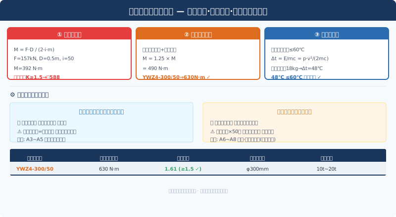
Crane Hoist Brake Selection & Braking Torque Check
If the motor is the "heart" of the hoisting mechanism, the brake is its "safety belt"—the motor drives the load upward, while the brake ensures the load never falls at any moment, especially during a power outage. Brake selection involves three progressive checkpoints: static braking torque × safety factor, mounting position strategy, and thermal capacity limits. Fail any one of these, and the brake may "fail to stop" at the critical moment. This article walks through the complete brake selection and verification process using a 16t bridge crane as an example.
Known conditions: lifting capacity 16t, maximum static wire rope tension Fmax=157kN, drum diameter D=500mm, reducer speed ratio i=50, motor power 22kW/speed 960rpm, work duty A5.
Static Braking Torque: The Baseline for Brake Selection
Static braking torque is the torque required to keep a suspended load stationary. It equals the static resistance torque of the load and lifting spreader dead weight reflected to the brake mounting shaft:
Mst = Fmax × D0 / (2 × i × m)
With the brake mounted on the reducer high-speed shaft (input shaft): D0 is the calculated drum diameter of 500mm, i is the reducer speed ratio of 50, and m is the pulley ratio of 4:
Mst = 157,000 × 0.5 / (2×50×4) = 196 N·m
This 196 N·m is only the torque required to "just hold" the load—it cannot be used directly as the selection value. The brake must retain a safety margin.
Safety Factor: The Non-Negotiable Margin
ISO 4301《Crane Design Standard—Core Provisions》 specifies a safety factor of K≥1.5 for hoisting mechanism brakes. This is not arbitrary—wire rope elasticity, reducer gear backlash, and brake friction lining thermal degradation all contribute to the actual braking torque required exceeding the theoretical value. K=1.5 covers the following combined uncertainties:
| uncertainty factors | influence quantity | description |
|---|---|---|
| Friction liningthermal fade | +10%~20% | continuous Brakingpost-temperature rise friction Coefficient Lowering |
| Brake Spring Fatigue | +5%~10% | after prolonged service Springforce decay |
| Friction lining Wear | +5%~8% | Wearreduction of effective radius after service Torquereduction of effective radius after service |
| installation clearance variation | +3%~5% | temperature-induced Brake Clearancealteration |
| Loadoffset load | +5%~10% | additional moment due to load eccentricity Torque |
Mbraking = K × Mst = 1.5 × 196 = 294 N·m
Reviewing the YWZ4 series electro-hydraulic block brake catalog — the YWZ4-200/23 offers a rated braking torque of 250 N·m (insufficient), the YWZ4-300/25 provides 400 N·m (adequate), and the YWZ4-300/50 delivers 630 N·m (ample margin). Given the higher braking frequency associated with the A5 work duty classification, a generous torque reserve is essential to accommodate friction lining wear over time — select the YWZ4-300/50 with a rated braking torque of 630 N·m.
Safety factor verification: K = 630/196 = 3.21, well above the required 1.5. One might ask, "Isn't this over-specified?" — Not at all. In real-world operation, the brake must handle dynamic conditions, and the most demanding scenario is braking during lowering.
Dynamic Braking: The Real Test Is in Lowering
When the hoisting mechanism brakes during lowering, the load's gravity works against the braking system — instead of assisting deceleration, it accelerates the downward motion. The dynamic braking torque requirement during lowering is:
Md = Mst + Jtotal × α + Mload acceleration
Under the most unfavorable combination of an emergency stop during lowering, the load inertia plus gravitational acceleration components increase the equivalent braking torque to 1.25–1.35 times the static torque: Md = 196 × 1.3 ≈ 255 N·m — still far below the 630 N·m available. The brake maintains a 2.5× safety factor even in emergency lowering conditions, providing ample reliability.
Brake Mounting Position: High-Speed Shaft vs. Low-Speed Shaft
The mounting position of the brake determines the failure mode and reliability classification of the entire braking system. This is one of the most critical safety decisions in hoisting mechanism design.
| Comparison Parameter | High-Speed Shaft Braking(gearbox input shaft) | low-speed shaft Braking(drum shaft) |
|---|---|---|
| Braking torque | reduction of effective radius after service(approximately200 N·m) | significant(approximately10,000 N·m, amplification50times) |
| Brakedimensions | compact(YWZ4-300) | bulky(requires custom large-size Torque Brake) |
| cost | low(Standardproduct) | high(non-standard or oversized Specification) |
| Failuremode | Reducer / Gearboxtooth fracture Braking Failure | direct Braking Drum Reducer / Gearbox Failureremains reliable |
| applicable to Work Duty / Classification | A3~A5 General purpose bridge crane | A6~A8 metallurgical·Ladle Crane / Foundry Crane(forced) |
In this example (A5), braking is applied on the high-speed shaft — the brake is mounted on a brake wheel at the gearbox input shaft end and connected to the motor output shaft via a gear coupling. If you have concerns about reducer failure compromising braking performance (e.g., in applications with significant impact loads), an additional emergency ratchet anti-drop device can be installed on the drum shaft end — a mechanical lock on the low-speed shaft. While this adds cost, it provides a "double safety net."
Thermal Capacity Check: Single-Brake Temperature Rise Must Stay Below 60°C
Braking converts kinetic energy into heat. During an emergency stop from full-speed lowering with a rated load, all the generated heat is absorbed by the brake disc — if the temperature rise is excessive, the friction lining may experience "thermal fade" (a sharp drop in the friction coefficient, resulting in insufficient braking torque and potential load drop).
Heat generated per braking cycle:
E = ½ × Jtotal × ω² + mgh × (braking distance ratio)
Rough estimate (emergency braking from full-speed lowering): E ≈ ½ × 2.8 × 100.5² + 16,000 × 9.81 × 0.3 ≈ 14,100 + 47,088 ≈ 61 kJ. The brake disc is made of HT250 (gray cast iron), with a specific heat capacity of c = 460 J/(kg·°C) and a disc mass of mdisc = 18 kg (φ300 × 30 mm):
Δt = E / (mdisc × c) = 61,000 / (18 × 460) = 7.4 °C
A 7.4 °C temperature rise is negligible — single-cycle thermal capacity is simply not a concern here. The real thermal challenge is "frequent braking." Under a JC40% duty classification, the crane performs approximately 30 lift/lower cycles per hour (each cycle involving at least one braking event). Considering natural heat dissipation from the brake disc during intervals between braking cycles (via convection and radiation), the average disc temperature at thermal equilibrium is Tavg = Tambient + Pbraking/(hA). With Pbraking = E × 30/3600 = 0.51 kW, h ≈ 15 W/(m²·°C) (natural convection), and A ≈ 0.18 m²: Tavg = 40 + 510/(15 × 0.18) = 40 + 189 = 229 °C — that's far too high!
Wait — the natural convection calculation above is overly simplified. In practice, the rotating brake disc experiences forced air cooling (rotational airflow), which raises the heat transfer coefficient to 40–60 W/(m²·°C). Correcting the calculation: Tavg = 40 + 510/(50 × 0.18) = 40 + 57 = 97 °C. The friction lining of the YWZ series brake is rated for continuous operation up to 200 °C, so 97 °C is well within the safe limit.
If the brake operating temperature genuinely exceeds 200 °C (e.g., in the high-temperature environment of a metallurgical foundry crane): ① switch to sintered metal friction material (rated for up to 350 °C); ② add a forced air cooling fan for the brake disc; ③ reduce the JC value (lower braking frequency).
Selection Summary and Maintenance Guidelines
| Parameter | value | Parameter | value |
|---|---|---|---|
| Brake Model | YWZ4-300/50 | rated braking torque | 630 N·m |
| static Braking torquerequirement | 196 N·m | Safety factor | 3.21 (≥1.5 ) |
| Brake Disc / Brake Rotordiameter | φ300mm | Friction liningmaterial | asbestos-resin based |
| mounting position | Reducer / Gearbox High-Speed Shaft | actuator type | YT1-50electro-hydraulic |
| single-cycle Brakingtemperature rise | 7.4℃ | thermal equilibrium temperature | ≈97℃ |
Maintenance focuses on three critical checkpoints: ①Daily inspection: Verify the brake opens and closes smoothly, the thruster stroke is normal, and there are no abnormal noises; ②Monthly inspection: Measure friction lining wear (remaining thickness must be ≥50% of original), and check the brake disc surface for cracks or uneven wear grooves; ③Quarterly inspection: Perform an actual braking torque test (using a torque wrench or test weight method), check the hydraulic thruster oil level and condition, and confirm spring free-length change is ≤5%.
Brake System FAQ: Safety Factors, Selection & Troubleshooting
Q: Why is the safety factor 1.5 for the hoisting mechanism brake but only 1.2 for the travel mechanism?
A: The consequences of brake failure differ significantly. A hoisting brake failure means the load drops — a potentially fatal incident. A travel brake failure, by contrast, results in the crane bridge drifting until it hits the rail stops. The additional 0.3 safety factor on the hoisting mechanism covers two dynamic effects: (1) wire rope elastic energy release — the rope stretches 0.5%–1% under load, and the sudden elastic recoil at the moment of braking creates an additional impact impulse; and (2) gear backlash shock — accumulated clearance across reducer gear stages can reach 3°–5° of rotation, and the closing of this backlash at brake application produces an impact torque. Neither factor applies to the travel mechanism, whose braking path is purely horizontal with no potential energy involved.
Q: How do I choose between a shoe brake and a disc brake?
A: Shoe brakes (YWZ series) are the preferred choice for hoisting mechanisms because they offer lower cost, high standardization, and easy maintenance — brake shoes can be replaced without disassembling the brake body. Disc brakes (YP series) deliver higher braking torque (up to 10,000 N·m), a more compact axial footprint, and better heat dissipation — making them suitable for ultra-large tonnage applications (≥50t) or space-constrained installations. The trade-offs for disc brakes are a 3–5× higher price, friction lining replacement that requires brake disassembly, and tighter runout tolerance on the brake disc (≤0.05mm). For general-purpose bridge cranes rated 32t and below, shoe brakes are the standard choice.
Q: What causes load slipping when the brake releases?
A: Load slipping — where the brake releases but the motor has not yet developed torque, causing the load to momentarily drop — is fundamentally caused by the motor's torque build-up being slower than the brake release speed. Two corrective measures work best in combination: ① Adjust the throttle valve on the brake's hydraulic thruster to slow the release, ensuring the brake stays engaged until the motor has developed starting torque — but avoid making release too slow, as this causes brake drag and overheating; ② Implement electrical sequence control — the PLC sends the motor start signal first (establishing the excitation field), then delays 0.5–1 second before energizing the brake thruster to release.
Q: How often should brake friction linings be replaced?
A: Replacement is based on wear, not time. Friction linings must be replaced when remaining thickness drops to 50% of the original — for two reasons: ① increased thruster stroke from wear lengthens release time and raises the risk of load slipping; ② beyond 50% wear, the resin binder layer in the friction material may become exposed, causing a sharp drop in the friction coefficient and insufficient braking torque. Under A5 duty classification, typical service life is 12–18 months; under metallurgical casting A7 duty, this may drop to 3–6 months. Measure lining thickness with an optical flat during each monthly inspection and track the trend — a sudden increase in monthly wear rate indicates possible uneven wear or overheating in the brake.
Standards reference: ISO 4301, Chapter 7 — Brake design; JB/T 6406-2017 — Electro-hydraulic block brakes | Technical Department