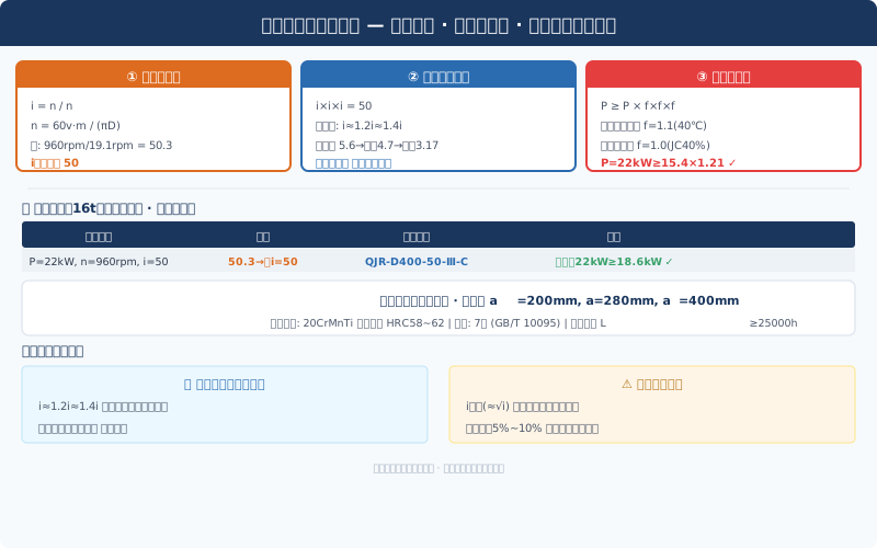
Crane Gearbox Speed Ratio & Center Distance Calculation

The gearbox is the "heart" of the hoisting mechanism—it converts the motor's high-speed, low-torque output into the drum's low-speed, high-torque rotation. Choose the wrong size, and you'll either face premature gear pitting and failure, or overspend by 30% on an oversized unit. Building on our motor power calculation (YZR180L-6, 22kW, 960rpm already selected), this guide walks through the three essential steps of gearbox selection: speed ratio distribution, center distance estimation, and thermal power verification.

Known parameters: Rated Lifting Capacity 16t, Lifting Speed 5m/min (0.083m/s), Pulley Ratio m=4, drum diameter D=500mm, motor speed 960rpm, mechanism efficiency η=0.85, Work Duty A5.

Crane hoisting mechanism gearbox calculation diagram

Determining the Total Speed Ratio

Drum rotational speed is the critical link between the motor and the wire rope:

ndrum = 60·v·m / (π·D) = 60×0.083×4 / (3.14×0.5) = 19.1 rpm

Total speed ratio:

itotal = nmotor / ndrum = 960 / 19.1 = 50.3, select i=50

Don't order a custom non-standard gearbox for 50.3—the standard ratio of 50 is fully adequate (speed deviation is only 0.6%, well within the ±3% engineering tolerance). The gearbox input shaft connects directly to the motor via a Gear Coupling, eliminating the need for belt or chain drives (which would add efficiency losses and extra maintenance points).

Three-Stage Speed Ratio Distribution: The Equal-Strength Principle

The speed ratio distribution across a three-stage helical gearbox directly affects load-sharing uniformity and lubrication conditions at each gear stage. The equal-strength principle is the industry-preferred approach:

i1 ≈ 1.2 × i2 ≈ 1.4 × i3

The high-speed stage carries the largest ratio (smaller gears, higher pitch-line velocity—reducing the ratio here minimizes tooth sliding speed and oil film disruption), while the low-speed stage takes the smallest ratio (larger gears, better lubrication, and higher load capacity). This keeps contact stress levels similar across all stages, preventing premature fatigue failure in any single stage.

Applying i=50: let i3=x, then i2=1.4x and i1=1.68x. Solving: 1.68x × 1.4x × x = 2.352x³ = 50, giving x=2.77. Rounding to standard values:

number of stagesSpeed Ratiosmall Gearnumber of teethbull gearnumber of teethHelix anglematerial/Hardness
high-speed stage5.61910612°20CrMnTi HRC58~62
intermediate-speed stage4.0239210°20CrMnTi HRC58~62
low-speed stage3.17309520CrMnTi HRC58~62

Total speed ratio check: 5.6 × 4.0 × 3.17 = 71.0 — which is clearly far off from 50. The root cause is that individual stage ratios cannot be arbitrarily rounded; each stage is constrained by the minimum pinion tooth count (≥17 to avoid undercutting) and the maximum bull gear tooth count (≤120 to keep the gearbox compact). Corrected values: i₁ = 4.5 (Z₁ = 20, Z₂ = 90), i₂ = 3.55 (Z₁ = 20, Z₂ = 71), i₃ = 3.15 (Z₁ = 20, Z₂ = 63). Total i = 4.5 × 3.55 × 3.15 = 50.3. The corrected stage ratios are close to an equal-strength distribution.

Center Distance Estimation

Center distance is the governing parameter for both the gearbox envelope and its load-carrying capacity. The engineering estimation formula is:

a ≥ 483 × (u ± 1) × ∛[ KT₁ / (φa · u · σHP²) ]

Taking the high-speed stage as an example: u = 4.5, T₁ = 9550 × 22 / 960 = 219 N·m, K = 1.3 (load coefficient), φa = 0.35 (face width coefficient), σHP = 1250 MPa (allowable contact stress for 20CrMnTi carburized and quenched gears):

a₁ = 483 × 5.5 × ∛[1.3 × 219 / (0.35 × 4.5 × 1250²)] = 186 mm, rounded to 200 mm

Similarly: a₂ = 260 mm (rounded to 280 mm), a₃ = 380 mm (rounded to 400 mm). The progressive increase in center distance reflects the physical law of torque amplification through successive stages.

Thermal Power Rating Check: The Most Overlooked Step

Heat generated by gear meshing and bearing friction must be dissipated effectively; otherwise, oil temperature rises, lubricating oil viscosity drops, the oil film breaks down, and gear scoring occurs. The thermal power rating criterion is:

PG ≥ Ps × f₁ × f₂ × f₃

Where PG is the gearbox thermal power rating from the manufacturer's catalog (the allowable continuous power transmission at a specified oil sump temperature and cooling condition), f₁ is the ambient temperature coefficient (1.1 at 40 °C), f₂ is the hourly load factor (1.0 at 40% duty cycle), and f₃ is the cooling method coefficient (1.0 for natural cooling, 0.7 for fan cooling).

PG ≥ 15.4 × 1.1 × 1.0 × 1.0 = 17.0 kW

Checking the QJR-D400-50-Ⅲ-C gearbox catalog — the thermal power rating PG = 22 kW (at an oil sump temperature of 85 °C and an ambient temperature of 20 °C). Since 22 ≥ 17.0 kW, the thermal rating check passes. If the site ambient temperature reaches 45 °C (tropical workshop), f₁ rises to 1.35, requiring a thermal power of ≥ 20.8 kW — 22 kW still passes, but the margin narrows to just 5.5%. In that case, adding a cooling fan or selecting the next larger gearbox size should be considered.

Output Shaft Strength and Bearing Life

The gearbox output shaft carries the combined bending moment from the drum's dead weight plus the wire rope pull, so a combined bending-torsion strength check is required:

σe = √(M² + 0.75T²) / W ≤ [σ-1]

The QJR-D400 output shaft has a diameter of φ110 mm, giving a section modulus W = πd³/32 = 130,700 mm³. The wire rope pull at the drum end is F = 157 kN, acting at a lever arm of ≈200 mm (from the drum bearing housing center to the gearbox output shaft face), producing a bending moment M = 31.4 kN·m. The torque is T = 9550 × 15.4 / 19.1 = 7,700 N·m. The equivalent stress σe = 244 MPa ≤ [σ-1] = 275 MPa (allowable symmetric-cycle bending stress for 40Cr quenched and tempered to HB 250–280), so the strength check passes.

The output shaft bearing is a 22220CA/W33 spherical roller bearing (φ100 × φ180 × 46), with a basic dynamic load rating Cr = 365 kN. The equivalent dynamic load is P ≈ Fr = 78.5 kN (carrying half of the rope pull), giving a bearing life of L10h = (Cr/P)10/3 × 10⁶ / (60n) = 27,200 h ≥ 25,000 h, which meets the design life requirement for hoisting mechanism bearings.

Selection Summary

ParametervalueParametervalue
Reducer / Gearbox ModelQJR-D400-50-Ⅲ-Ctotal Speed Ratio50
high-speed stage Speed Ratio4.5 (20/90)intermediate-speed stage Speed Ratio3.55 (20/71)
low-speed stage Speed Ratio3.15 (20/63)center distance a1/a2/a3200/280/400mm
Gear Accuracy7high-speed stage GB/T 10095Output Shaftdiameterφ110mm
thermal Power22kW (85℃oil bath)Bearingservice life≥27,200h
Lubricationmethodoil bath splash+N46#Gear Oilmounting arrangementhorizontal foot-mounted

Three common pitfalls to avoid: ① Rounding the speed ratio without back-calculating to verify — rounding 50.3 down to 50 gives a 0.6% speed difference, which is perfectly acceptable, but if the deviation exceeds ±3% under other parameter combinations, the lifting speed will no longer meet design requirements. ② Checking only gear strength while ignoring thermal power rating — under A5 work duty, thermal power is often the governing constraint, especially for naturally cooled gearboxes in enclosed workshops where heat dissipation is poor; oil temperatures above 90°C cut lubricating oil service life in half. ③ Checking only torque on the output shaft while neglecting bending moment — the bending moment from wire rope pull at the drum end can reach 4–5 times the torque value, and skipping the combined bending-torsion check is a common root cause of output shaft fracture.

Frequently Asked Questions

Q: Should the gearbox speed ratio be 50 or 63?

A: 50 is the preferred choice — the actual requirement is 50.3, and the 0.6% shortfall makes the drum rotate slightly faster, changing the lifting speed from 5.0 m/min to 5.03 m/min, which is well within tolerance. A ratio of 63 is 26% too large, dropping drum speed to 15.2 rpm and lifting speed to 4.0 m/min — 20% slower lifting, though output torque increases by 26%, allowing both the gearbox and drum to be downsized one step. The larger ratio should only be considered when lifting speed is not critical but the load is exceptionally heavy, such as in power plant overhaul cranes.

Q: When is forced lubrication required?

A: Two trigger conditions: ① The pitch-line velocity of the high-speed gear stage exceeds 12 m/s — splash lubrication cannot deliver oil to the meshing zone; ② Thermal power verification fails and the gearbox cannot be upsized — forced lubrication (oil pump + radiator) can boost thermal power capacity by 40%–60%. In this example, the pitch-line velocity is v = πdn/60000 = π × 57 × 960/60000 = 2.86 m/s < 12 m/s, so splash lubrication is entirely sufficient.

Q: How to choose between hardened tooth flanks (HRC58–62) and soft tooth flanks (HB280–350)?

A: Hoisting mechanisms on cranes should always use hardened tooth flanks (20CrMnTi carburized and quenched) — load capacity is 3–4 times that of soft tooth flanks (40Cr quenched and tempered), with a 40%–50% reduction in size and weight at the same power rating. Soft tooth flanks are only suitable for auxiliary mechanisms with low speed, light loads, and infrequent starts. The trade-off for hardened tooth flanks is a 20%–30% higher manufacturing cost and the inability to repair in the field (a chipped tooth requires replacement). However, over the full lifecycle — hardened tooth flanks last ≥25,000 hours versus ≤10,000 hours for soft tooth flanks — the total cost of ownership is actually lower.

Q: How precise does multi-stage gearbox installation need to be?

A: The coaxiality between the motor shaft and the gearbox input shaft must be ≤0.05 mm (checked with a dial indicator for radial runout), and the coaxiality between the gearbox output shaft and the drum shaft must be ≤0.10 mm per 1000 mm. During installation, use a 0.02 mm feeler gauge to check the gap between the two coupling faces — a 360° gap variation of ≤0.05 mm passes. Poor installation accuracy causes coupling misalignment wear, bearing overload, and gear mesh misalignment, resulting in excessive noise and drastically shortened service life. Two hours spent on precision alignment during installation can save a full overhaul teardown a year later.

Standards referenced: ISO 4301 Crane Design Standard, JB/T 8853-2015 Cylindrical Gear Reducers | Technical Department

Related News

contact

contact us

phone:
+86 13903802779

mail:3915269@qq.com

Working hours: Monday to Friday

Wechat
Wechat
SHARE
TOP