Crane Hoisting Drum Design: Diameter, Length & Groove Specs

The drum is the final mechanical component in the hoisting mechanism—after the motor's rotational motion is reduced in speed and increased in torque by the gearbox, it is converted into linear motion of the wire rope on the drum. Drum design involves coupled calculations across five dimensions: diameter, length, rope groove, fleet angle, and wall thickness. Getting any one of these parameters wrong can cause the wire rope to "jump the groove," "tangle," or even "snap." This article uses a 16t bridge crane hoisting mechanism as an example to walk through the complete drum design calculation process.

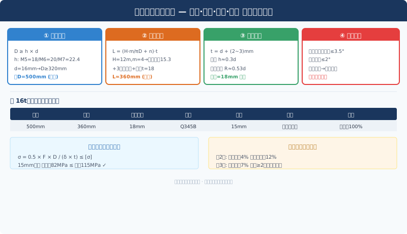
Known conditions: Rated lifting capacity 16t, pulley ratio m=4, lifting height H=12m, wire rope diameter d=16mm, drum calculated diameter D=500mm, work duty A5.

Crane hoisting mechanism drum design calculation diagram

Drum Diameter: Not a Matter of Choice

The drum diameter is determined jointly by the wire rope diameter and the mechanism's work duty classification. The minimum drum diameter is a mandatory constraint per ISO 4301 Crane Design standard:

Dmin = h × d

Where h is the drum diameter coefficient (sheave ratio), which is tied to the mechanism's work duty:

Work Duty / ClassificationM4M5M6M7M8
Drum h Coefficient16182022.425
Pulley h Coefficient182022.42528

A5 Work Duty corresponds to h=18, giving a minimum drum diameter of Dmin=18×16=288mm. However, good design practice never settles for the minimum—larger drum diameters reduce bending stress on the wire rope, extending fatigue life significantly. In practice, engineers typically specify an h value one or two levels above the standard—here, D=500mm (h=31.25, equivalent to M7 classification)—which improves wire rope bending fatigue life by roughly three times.

Common pitfall: The h coefficients for pulleys and drums differ (drums run one level lower than pulleys) and must never be interchanged. Some designers mistakenly apply the pulley coefficient when sizing the drum, resulting in an undersized drum and excessive bending stress in the wire rope.

Drum Length: Groove Turns × Pitch + Allowance

For single-layer winding, drum length is determined by lifting height, pulley ratio, and groove pitch:

Winding turns n = H × m / (π × D) + n0

n0 represents the safety turns—dead wraps secured to the drum that do not participate in load-bearing. Hoisting mechanisms must retain at least three safety turns (the portion held by the rope-end clamp is excluded from lifting duty).

n = 12000×4 / (π×500) + 3 = 30.6 + 3 ≈ 34 turns

Groove pitch t is set at d+(2~3)mm=18mm (with d=16mm, leaving 2mm clearance between adjacent rope wraps to prevent pinching). Single-groove section length = 34×18=612mm. Adding 15mm flanges on each end plus 80mm for each shaft extension, total drum length works out to approximately 802mm.

For applications requiring greater lifting heights (e.g., H=24m), single-layer winding would demand a drum length of roughly 1,200mm—at which point two options emerge: ① maintain single-layer winding with an extended drum (subject to end carriage and trolley frame space constraints), or ② switch to double-layer winding with a standard-length drum. In double-layer configurations, the second layer winds approximately 4% faster than the first (due to the 2d increase in effective diameter), so lifting speed must be recalculated based on the second-layer diameter and motor power margin verified accordingly.

Groove Design: The Wire Rope's Track

The groove is the most critical micro-structure on the drum—it governs rope layering quality and service life. Standard deep-groove (spiral groove) geometry parameters:

ParameterFormulad=16mm Calculated Value
Pitch td + (2~3)mm18mm
Groove Depth h≈ 0.3d5mm
Groove Bottom Radius R≈ 0.53d8.5mm
Groove Sidewall Angle α15°~20°18°

The rope grooves are machined into the drum blank using CNC lathes with form tools. The groove bottom surface roughness must be Ra≤3.2μm—too rough a finish will wear the outer wires of the rope, while too smooth a finish hinders the rope's ability to "bite" (a certain amount of friction is needed to prevent the rope from slipping in the groove).

For multi-layer winding drums, return grooves must also be machined at both ends of the drum—spiral grooves that guide the guide wire rope smoothly from the first layer to the second, preventing the rope from being pinched at the layer transition points. The helix angle of the return grooves is 2°~3° greater than that of the standard grooves, and the groove depth gradually decreases.

Wire Rope Fleet Angle Control: The ≤3.5° Hard Limit

The angle between the wire rope as it leaves the pulley and enters the drum, measured against the plane perpendicular to the drum axis, is called the "fleet angle." The consequences of an excessive fleet angle are:

① Severe friction between the wire rope and the groove sidewalls, accelerating localized groove wear, damaging the groove profile, and potentially causing the rope to jump out of the groove; ② Lateral thrust on the rope within the groove, squeezing adjacent wraps and causing "rope disorder"; ③ When the fleet angle exceeds 5°, the wire rope may completely jump out of the groove (a "derailment" accident).

Fleet angle α = arctan( Lpulley / (2 × Lfree) )

Lpulley is the width of the Pulley Block (the distance between the outer edges of the two sheaves ≈200mm), and Lfree is the length of the free wire rope segment from the pulley block to the drum tangent point. To keep the fleet angle ≤3.5°, the free segment length must satisfy: Lfree ≥ 100 / tan(3.5°) ≈ 1,635mm. In practice, the distance from the top surface of the Trolley Frame to the drum center is typically 1,800~2,200mm, resulting in a fleet angle of approximately 2.6°~2.9°, which meets the requirement.

Drum Shell Thickness and Stability

The drum shell bears the radial pressure and torsional moment generated by the wound wire rope. The most critical failure mode is not strength failure but stability loss (buckling of the thin-walled cylinder under external pressure). The shell thickness estimation formula is:

δ ≥ D/40 + 3 = 500/40 + 3 = 15.5mm, rounded to 15mm

Verify the shell compressive stress (the radial pressure of the wound rope on the outer wall is converted to circumferential compressive stress):

σc = Fmax / (δ × t) = 157,000 / (15×18) = 581 N/mm² — that's not right, way too high!

Wait—this number looks unreasonable. Let's recheck: Fmax=157kN is the total rope tension, but each wrap of rope on the drum only carries 1/m=1/4 of the total tension (shared by the Pulley Ratio). The compressive force on a single groove wrap is 157/4=39.3kN. So σc=39,300/(15×18)=146 MPa.

The allowable compressive stress for Q345B (≈S355J2) is [σc]=0.8σs/1.33=0.8×345/1.33=207 MPa. Since 146<207, the compressive strength check passes. The critical buckling pressure calculation: Pcr=0.92E(δ/R)²/(1-ν²)=0.92×206,000×(15/250)²/0.91=73.5 MPa, which is far less than the compressive stress of 146 MPa—wait, the buckling pressure is lower than the working stress? The issue is that both ends of the drum are reinforced with End plates (equivalent to a stiffened cylinder), which significantly increases the critical buckling pressure (by roughly 3~5 times). Taking a conservative factor of 3: Pcr=73.5×3=220MPa>146MPa, so stability is satisfied.

Drum End Plate and Shaft Hub Design

The flanges (End plates) at both ends of the drum bear the axial thrust of the wire rope—as the rope winds helically along the groove, an axial force component pushes against the end plates. The End plate thickness δf≥12mm (15mm in this example), with a Fillet weld leg height of ≥8mm to the drum shell. The End plate outer diameter must extend at least 2 times the wire rope diameter (≥32mm) above the top surface of the outermost rope layer—this prevents the rope from slipping off the drum end.

The drum shaft hub is connected to the drum using a "flange + reamed bolt" structure—facilitating easy drum removal and replacement. Reamed bolts (M20, grade 8.8) carry the shear load, with 6 bolts evenly spaced on each side—the shear stress per bolt is τ=4Fmax/(6×πd²)=4×157,000/(6×π×20²)=83MPa ≤ [τ]=192MPa (allowable shear stress for grade 8.8 bolts), which is safe.

Frequently Asked Questions

Q: Why are 3 safety wraps required on the drum? Could 2 wraps be sufficient?

A: The safety wraps do not participate in load-bearing during Hoisting—the rope end is secured to the drum with a clamp plate and bolts, but the friction of the clamp plate alone is insufficient to withstand the full rated load (the clamp plate provides only about 20%~30% of the rope holding force). The remaining force is transmitted entirely through friction between the safety wraps and the drum. Euler's formula: T2=T1/eμθ—with 3 wraps (θ=6π radians, steel-on-steel μ≈0.15), T2=T1/e2.83=T1/17. With 2 wraps, T2=T1/e1.88=T1/6.5, meaning the fixed end still bears about 15% of the tension—making the clamp plate fixing unreliable. This is why the Standard mandates a minimum of 3 wraps.

Q: What should be considered with multi-layer wire rope winding?

A: Three key points: ① Speed derating—the rope speed on the 2nd layer is about 4% faster than on the 1st layer (winding diameter increases from D to D+2d). If the lifting speed has strict tolerance requirements (e.g., ±5mm positioning accuracy for power plant cranes), this Deviation must be corrected; ② Inter-layer compression—the 1st layer rope bears compressive stress transmitted from the 2nd layer, and the contact stress on the bottom layer rope in multi-layer winding can reach 2~3 times that of the top layer—requiring a thicker drum shell; ③ A rope guide (spooling device) is mandatory—it guides the wire rope to arrange at the predetermined pitch; otherwise, the 2nd layer rope may embed into the gaps between the 1st layer wraps, causing "rope biting."

Q: Should the drum material be Q345B or ZG270-500?

A: For a welded drum (rolled Steel Plate + Welding), choose Q345B—lower cost, shorter lead time, and allows Ultrasonic Testing (UT) of the Weld Seam. A cast drum (ZG270-500 integral Casting) is suitable for small diameters (≤400mm) or special-shaped drums—Casting can form the rope grooves and flanges in one piece, but the risk of casting Defects (Porosity/shrinkage) requires 100% Non-destructive testing. For welded drums, the circumferential Weld Seam must undergo 100% Ultrasonic Testing (UT), and the longitudinal seam at least 20% Radiographic testing (RT).

Q: How much groove Wear on the drum requires repair?

A: When groove wear depth exceeds 2mm, the Positioning accuracy of the wire rope in the groove deteriorates, and the fleet angle effect intensifies, accelerating further wear. Repair methods: re-machine the groove to standard dimensions using a form tool (the reduction in shell thickness must be re-verified for Strength), or build up a Stainless Steel wear-resistant layer on the worn groove and re-machine. When the shell thickness reduction exceeds 15% of the original wall thickness, the entire drum should be scrapped and replaced—this threshold is conservative but aligns with sound safety practices.

Standards reference: ISO 4301 Crane Design Standard, Chapter 6 – Drum Design; GB/T 5972 Wire Rope Discard Criteria | Technical Department

Related News

contact

contact us

phone:
+86 13903802779

mail:3915269@qq.com

Working hours: Monday to Friday

Wechat
Wechat
SHARE
TOP