

3D Laser Scanning for Overhead Cranes: Field to Digital Twin
3D Laser Point Cloud Scanning for Overhead Cranes uses a laser scanner to rapidly capture the crane's geometry on-site, delivering point cloud data with ±2mm accuracy. This data is then reverse-engineered into usable CAD/BIM models, providing a precise 3D foundation for the crane's Digital Twin system. A single crane can be scanned and modeled in just 1–3 days, with no original drawings required.
A Digital Twin for an overhead crane relies on an accurate 3D model as its foundation—but for many existing cranes, the original CAD drawings are long gone. 3D laser point cloud scanning solves this problem: a laser scanner captures the crane on-site in a single pass, producing high-precision point cloud data that is then reverse-engineered into a usable CAD model.
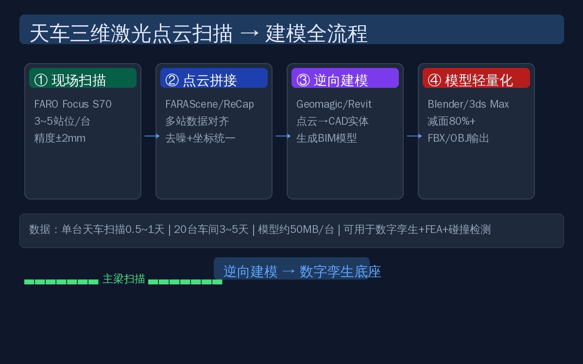
| Procedure | Work Scope | Tools | Duration |
|---|---|---|---|
| 1. On-site Scanning | Station-based Scanningoverhead cranesteel structure+Crane Rail+Factory building | Ground3D laser scanner | 0.5~1Day(s) |
| 2. Point Cloud Registration | Multi-station Data Registration+Noise Filtering+Coordinate Unification | FARAS (Australian Standard)cene/Re Cap | 0.5Day(s) |
| 3. Reverse Modeling | Point Cloud Generation CADSolid Model | Geomagic/Revit | 1~2Day(s) |
| 4. Solid Modellightweight design | Mesh Decimation+Format Conversion | Blender/3ds Max | 0.5Day(s) |
Recommended scanner: FARO Focus S70 (scanning accuracy ±2mm/10m, scanning range 0.6–70m, speed 976,000 points/sec). A single overhead crane typically requires 3–5 scan stations (covering the main girder top/bottom/sides, end carriages, and crane rail). Scanning 20 cranes in one workshop takes approximately 3–5 days. The reverse-engineered model can be used for Digital Twin visualization, finite element analysis, collision detection, retrofit design, and other applications.
Laser Scanner Selection Criteria for Crane Scanning
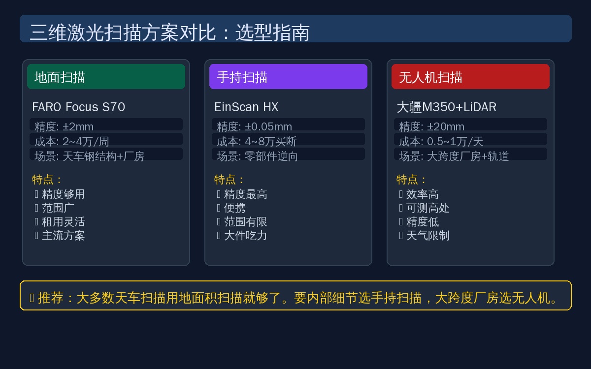
The 3D laser scanner is the core equipment for overhead crane point cloud modeling. Scanner selection directly impacts scanning efficiency and modeling accuracy. Three mainstream solutions dominate the market, each suited to different Application Scenarios.
FARO Focus Series (e.g., Focus S70/S150): Ranging accuracy ±1mm/10m; the S70 covers 0.6–70m and the S150 reaches 0.6–150m, with a scanning speed of 976,000 points/sec. The built-in color camera captures synchronized RGB information, making it ideal for full steel structure scanning of overhead cranes. Environmental requirements: operating temperature 5–40°C, Protection Rating (IP) IP54, suitable for typical factory building environments. Single-station scan time is approximately 3–7 minutes (at 1/4 Resolution), making it the preferred choice for the vast majority of crane scanning projects.
Leica RTC360: Accuracy ±1mm/10m, scanning speed 2 million points/sec, with VIS tracking technology enabling target-free registration. Its biggest advantages are fast scanning speed (approximately 2 minutes per station) and on-site real-time preview capabilities. Well-suited for large crane workshops with tight deadlines. However, the equipment cost is roughly 30–40% higher than FARO, and rental costs are correspondingly higher as well.
Z+F 5016: Accuracy ±1.5mm/10m, scanning range 0.3–360m, with line-scan technology offering strong resistance to dust interference. For Dusty Environment Service applications such as foundries and steel mills, the Z+F's Dustproof performance is notably superior to FARO and Leica. The drawback is its heavier weight (approximately 14kg), making it less portable than the other two options.
Selection recommendations: Choose the FARO Focus S70 for standard factory building cranes (best cost-performance); opt for the Leica RTC360 when schedules are tight (over 50% faster); select the Z+F 5016 for high-dust environments (superior dust resistance); for reverse modeling of individual Components only, consider a handheld scanner such as the EinScan HX.
On-Site Scanning Execution Workflow
On-site scanning is the critical step that determines point cloud data quality. Improper execution can lead to registration difficulties and even require rework. The following workflow is based on experience from scanning hundreds of overhead cranes.
Scan Station Planning: A standard configuration for a single crane uses 3–5 stations. Station 1 is positioned on the ground center below the crane to capture the main girder underside and both end carriages; Station 2 is located on one side of the end carriage to cover the main girder side and wheels; Station 3 is placed at a diagonal position to supplement data from the other side. For cranes with a Span exceeding 25 meters, add Stations 4–5 in the middle to ensure complete coverage of the main girder top surface and crane rail data. Station spacing is generally kept between 10–15 meters to maintain a point cloud overlap of over 60% between adjacent stations.
Target Placement: Affix 6–8 spherical targets (approximately 3.8cm diameter) to fixed objects (e.g., Columns, walls) in each scan area, ensuring at least 3 common targets are visible within each station's field of view and covered by adjacent stations. The more securely targets are fixed, the higher the registration accuracy. When transforming the measurement coordinate system within the workshop, use a total station to determine the absolute coordinates of at least 3 control points as a reference.
Scan Parameter Settings: For crane steel structures, use 1/4 Resolution (approximately 6mm point spacing at 10m) to balance speed and accuracy; switch to 1/2 Resolution (approximately 3mm point spacing at 10m) for fine details such as wheels, Hooks, and Weld Seam areas. For color scanning, ensure adequate indoor lighting and avoid direct strong light that could cause uneven exposure.
Environmental Considerations: Avoid large Machinery vibration during scanning (e.g., stamping presses, centrifuges), as vibration can cause point cloud drift. Insufficient lighting does not affect scanning accuracy but degrades camera capture quality. Extremely high dust concentrations may attenuate laser return signals; it is advisable to schedule scanning during maintenance shutdowns or use Z+F series scanners with enhanced dust resistance.
Point Cloud Registration and Processing
Raw point cloud data from multiple scan stations resides in independent local coordinate systems. Registration merges these into a unified coordinate system, followed by filtering and denoising before modeling can proceed.
Multi-Station Registration Algorithms: Two primary registration methods are used. Target-Based Registration calculates rigid transformation matrices (optimized via the ICP algorithm) using the center coordinates of common spherical targets scanned at each station. This offers the highest accuracy, with residuals controllable to within ±2mm. Both FARO Scene and Leica Register360 support automatic target Identification and alignment. Cloud-to-Cloud Registration (feature-based) is suitable when targets are missing; it automatically matches adjacent stations by extracting geometric features (planes, cylinders, corners) from the point cloud. Accuracy is approximately ±5mm, making it suitable for rapid previews, though target-based verification is recommended for formal projects. Crane workshops typically employ a hybrid approach: target-based registration for main structures to ensure precision, supplemented by feature-based registration for edge details.
Point Cloud Denoising and Filtering: Three types of noise arise during scanning: outlier noise (flying points, specular reflections) is removed using statistical filtering—setting a neighborhood point count (e.g., 30) and removing points deviating more than 2 standard deviations from the mean; thin-wall noise (diffuse points at steel structure edges) is cleaned using radius filtering; moving object noise (personnel walking, crane sway) requires manual box selection and deletion. A 100GB raw point cloud dataset can typically be reduced by approximately 15–30% of redundant data after denoising.
Coordinate System Unification: All point clouds must ultimately be transformed into either the crane's local coordinate system or the factory building coordinate system. The crane's local coordinate system defines the main girder centerline as the X-axis, the end carriage direction as the Y-axis, and vertical upward as the Z-axis. Using control point coordinates measured by the total station, a seven-parameter coordinate transformation (Bursa model) is performed using 3–6 common spatial points, with transformation residuals controlled to within ±3mm.
Data Volume Estimation: Scanning 3–5 stations for one crane generates approximately 30–80GB of raw point cloud data (including color information). After registration and denoising, this reduces to about 20–50GB. Considering ongoing storage costs and downstream modeling efficiency, it is recommended to archive the simplified, post-registration version (approximately 5–10GB per crane) and retain raw data only until project Acceptance.
Reverse Engineering Modeling Methods
Point cloud reverse engineering converts discrete point cloud data into editable CAD/BIM models—the most technically demanding and time-consuming stage of the entire workflow.
Modeling Tool Selection: Geomagic Design X is the standard tool for industrial reverse engineering, supporting solid and surface modeling directly from point clouds with automatic fitting of planes, cylinders, spheres, and other basic geometric primitives. It is well-suited for crane steel structures, which consist primarily of regular geometries—main girder boxes, End Carriages, and rails can be quickly generated via fitting. Output in universal formats like STEP/IGES for use in SolidWorks/CATIA design. Autodesk Revit is appropriate for crane projects requiring integration with building structural information, placing the crane model directly into the factory building BIM model for collision detection and space management. For Digital Twin visualization, use Blender or 3ds Max for mesh decimation and texturing, then export to FBX/OBJ formats.
Modeling Workflow: Step 1 Data Preprocessing: In Geomagic Wrap, encapsulate the denoised point cloud into a mesh, repairing holes and self-intersections—this typically automates about 80% of the work. Step 2 Feature Extraction: Identify key crane structures (Main Girder, End Carriage, Walkway / Platform, guardrails, Crane Rail, wheels, Hook) and extract their outlines and cross-sections. Step 3 Solid Modeling: Convert extracted features into parametric solids, rebuilding the complete model in Design X or Revit. Step 4 Accuracy Verification: Perform deviation analysis (3D Compare) between the generated CAD model and the original point cloud; main structure deviations should be controlled to within ±5mm.
Model Accuracy Control: Different crane components have varying accuracy requirements. Grade A Accuracy (±2mm): Hook center, Wheel Flange, and rail working surfaces—these affect crane operational safety and lifting accuracy and must be modeled with precision. Grade B Accuracy (±5mm): Main girder profile, end carriage connection faces, and walkway structures—these impact dimensional matching for retrofit designs. Grade C Accuracy (±20mm): guardrails, walkway grating, and electrical control box enclosures—schematic placement suffices. Tiered modeling can save over 40% of modeling time.
LOD Levels: Referencing BIM standards, crane models are recommended to be built in three levels. LOD200 is suitable for scheme presentation and layout analysis; LOD300 is appropriate for retrofit design and collision detection; LOD350 is required for construction drawing design and component fabrication. Most crane Digital Twin projects achieve sufficient detail at LOD300, with refinement to LOD350 only as needed.
Scanning Solution Comparison
Kelude Heavy Industry: Overhead Crane & Gantry Crane Solutions
Kelude Heavy Industry specializes in the design and manufacture of industrial overhead cranes and gantry cranes. Our product range covers a wide spectrum of applications, from single-girder and double-girder bridge cranes to versatile gantry systems and specialized explosion-proof configurations. We provide complete material handling solutions tailored to the specific needs of workshops, warehouses, and production lines.
Real-World Retrofit Case Study
A steel mill operates 25 overhead cranes, 12 of which have been in service for over 15 years with their original CAD drawings lost. In 2025, the mill plans to retrofit 8 of these cranes with intelligent automation (adding automatic positioning and a remote monitoring system). However, the retrofit design requires precise 3D crane dimensions and on-site installation clearance data. The solution: using a FARO Focus S70 to scan all 8 cranes one by one, with 3–5 scan stations per crane, completing the entire scan in 5 days. The reverse-engineered model was exported in Revit format and imported directly into the retrofit design software. The design phase was shortened from an estimated 3 months to just 1 month—eliminating manual measurements and on-site drawing verification. The total cost for scanning and modeling was approximately $11,800, but the time saved in design and the reduction in field rework far exceeded this investment.
Frequently Asked Questions
Q: Is point cloud scanning accurate enough for design work?
A: The FARO Focus S70 offers a scanning accuracy of ±2mm at 10m, which is more than sufficient for overhead crane steel structure modeling. The dimensional tolerance for crane main girders is typically ±5mm, so 2mm accuracy far exceeds design requirements.
Q: Does scanning require production shutdown?
A: No extended shutdown is needed. Scanning a single crane takes about 0.5–1 day, which can be scheduled during planned maintenance or weekends. All 20 cranes in a workshop can be scanned in batches over 3–5 days.
Q: Can the scanned model be used directly for Digital Twin applications?
A: Yes. The reverse-engineered model can be exported in FBX or OBJ formats and imported directly into engines like Unity3D or Three.js. Each model is approximately 50MB per crane, which loads smoothly on mainstream browsers and mobile devices.
