

Circular Rail Crane Design: Track Bending & PLC Control
The Complete Guide to Custom Circular Rail Cranes: Rail Bending, Wheel Self-Alignment, and PLC Differential Control. A circular rail crane is a specialized lifting appliance that travels along an arc-shaped track, commonly used in nuclear power plant reactor buildings (polar cranes), circular tank farms in chemical plants, turbine maintenance bays in hydroelectric stations, and wind tower assembly workshops.
A circular rail crane is a dedicated lifting appliance that operates on a curved track, typically deployed in nuclear reactor buildings (polar cranes), chemical plant circular tank farms, hydroelectric turbine maintenance areas, and wind tower assembly shops. Compared to straight-track systems, the manufacturing, installation, and wheel design for circular rails differ fundamentally—standard rail profiles cannot be laid directly along an arc, wheels must self-align automatically on the curve, and collision avoidance between multiple cranes sharing the same circular track adds further complexity. Drawing on extensive non-standard design experience from nuclear polar cranes and chemical tank farm installations, Kelude has systematically compiled the key design considerations for circular rail cranes, covering rail manufacturing accuracy, wheel differential speed control, PLC-servo synchronization, conductive slip ring power supply, and anti-derailment safety systems.
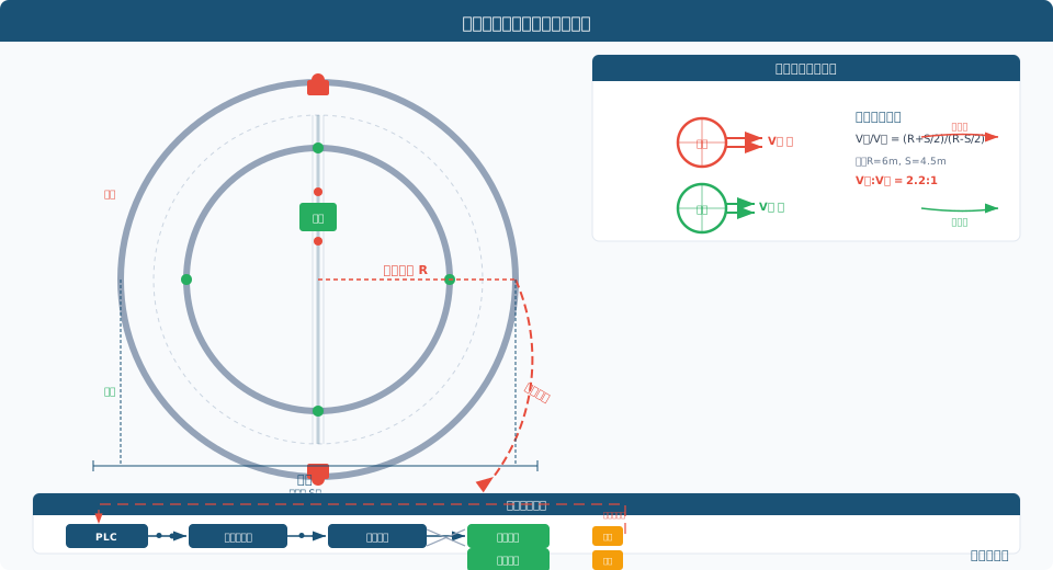
Circular Rail Manufacturing and Installation
The manufacturing precision of the circular rail directly determines the crane's running smoothness and wheel service life. Arc rails are typically formed from QU-series crane rails (QU70/QU80/QU100) bent to a specified radius of curvature. Two bending methods are used: cold bending, suitable for radii ≥5 m, employs a three-roll bending machine to curve the rail incrementally, with post-bend curvature deviation checked to ≤±2 mm/m; hot bending is reserved for tight radii below 5 m, using flame heating at 800–950°C followed by normalizing to relieve internal stress, achieving a minimum bend radius of 2 m.
Rail joints are cut at a 45° bevel, with a joint gap ≤3 mm and vertical offset ≤0.5 mm. Butt welds must undergo 100% Ultrasonic Testing (UT) in accordance with GB/T 11345. A transition section with gradually varying curvature—from infinite radius down to the design value—is provided where the circular rail meets straight track, with a transition length ≥3 m to ensure smooth wheel passage. Each bent rail segment is limited to ≤6 m along the arc for ease of transport and handling; after bending, a trial assembly is carried out on a dedicated jig to verify overall curvature accuracy. Key installation tolerances: radial deviation ≤±5 mm, elevation deviation ≤±3 mm, and rail surface levelness ≤1/1000. Upon completion, a no-load test run is mandatory—the trolley must complete three continuous circuits around the ring at rated speed, with no wheel rail gnawing, abnormal noise, or excessive temperature rise before acceptance.
Circular Rail Accuracy Requirements
The geometric accuracy of the circular rail is fundamental to long-term stable crane operation. In accordance with ISO 4301 Crane Design Standard and GB/T 10183 Tolerances for Bridge and Gantry Crane Rails, the following parameters must be controlled simultaneously: track gauge deviation not exceeding ±3 mm over the full circumference; radial deviation of the rail centerline from the theoretical cylindrical surface within ±5 mm; elevation difference between the two rail tops at any cross-section within ±3 mm; and longitudinal rail slope ≤1/1000. For demanding applications such as nuclear polar cranes (radius R=8–15 m), radial deviation is tightened to ±2 mm and elevation deviation to ≤±1.5 mm, requiring laser tracker measurement and adjustment on a segment-by-segment basis.
Straightness inspection of a circular rail cannot rely on the wire-stretching method used for linear tracks; instead, a total station or laser tracker (measurement accuracy 0.5 mm + 5 ppm) must be used to measure points along the rail centerline. Measurement points are spaced at ≤500 mm intervals, with no fewer than 36 points per full circuit. After least-squares fitting of the measured data, the offset between the actual and theoretical curvature centers is calculated—the allowable offset is ≤5 mm. Local reinforcement is applied at rail joints: a base plate at least 12 mm thick, made of Q355B (≈S355JR), is installed over a 500 mm zone on each side of the joint. The rail system also incorporates expansion joints with a gap of 6–10 mm, spaced according to thermal expansion calculations (one joint per 100 m of rail). Thermal expansion of the circular rail is calculated using the formula ΔL=α·L·Δt (α=11.5×10⁻⁶/°C); with a working temperature differential of 40°C, a 100 m rail expands approximately 46 mm, which must be fully accounted for in the rail fixing method and expansion joint design.
PLC-Servo Drive and Control System
The control system for a circular rail crane adopts a three-tier architecture of "PLC + servo drive + bus communication," with the core task of ensuring safe, coordinated operation of multiple cranes on the same circular track. The PLC is a Siemens S7-1500 or equivalent controller (cycle time ≤10 ms), paired with SEW-Eurodrive MoviDrive or Lenze i950 series servo drives supporting PROFINET IRT real-time communication (jitter <1 μs).
Multi-crane collision avoidance employs a two-level strategy combining zone interlocking with PLC-based scheduling. At the first level, each crane is equipped with either a LiDAR sensor (detection range 0.5–30 m, angular resolution 0.1°) or a millimeter-wave radar (detection range 0.3–50 m) to continuously monitor the distance and relative speed of obstacles ahead. At the second level, each crane's PLC exchanges position, speed, and direction data over the PROFINET bus; when the gap between cranes falls below the safe threshold, automatic deceleration or stopping is triggered. Safe distances are set per ISO 4301 and GB/T 28264 Safety Monitoring and Management System: ≥5 m when traveling in the same direction, ≥3 m when traveling in opposite directions, and doubled to ≥10 m in crossing zones.
A hardwired interlock loop serves as the ultimate safety barrier—should the PLC system fail or bus communication be lost, the hardwired circuit directly cuts drive power to cranes entering a hazardous area, with a response time of ≤20 ms. Position feedback combines an incremental encoder (resolution 2048 P/R) with RFID landmark correction (RFID tags placed every 30°, reading accuracy ±1 mm) to eliminate cumulative error over long-distance travel. The multi-crane scheduling algorithm supports priority settings and task preemption—in nuclear polar crane applications, the main hoist crane is assigned higher priority than auxiliary cranes, ensuring critical lifts are never interrupted by avoidance logic. The operator interface uses a 15-inch touch screen (HMI) with 1280×800 resolution, displaying the real-time position and status of each crane on a top-down view of the circular track for intuitive supervision.
Conductive Slip Ring Power Supply System
Standard cable reels cannot be used to power a circular rail crane, as the closed-loop travel path prevents the cable from paying out and winding back. Kelude employs a combined conductor rail and conductive slip ring solution: an enclosed conductor rail is installed along the outer side of the circular track (three-phase four-wire configuration, copper busbar cross-section 40×5 mm, rated current ≥250 A); a current collector with carbon-copper alloy brushes mounted at the center of the main girder draws power by sliding along the conductor rail. The brush contact voltage drop is ≤0.3 V, with a service life of ≥100,000 m of sliding travel.
In multi-crane installations sharing a single circular track, each crane is fitted with its own independent current collector and slip ring enclosure, so power take-off points do not interfere with one another. The conductor rail is fed in segments: a power feed point is provided every 90° (quarter circle), each independently supplied from a power distribution cabinet, ensuring that a fault in one segment does not interrupt power around the entire ring. The conductor rail has an IP54 Protection rating, with silver-plated joints keeping contact resistance ≤0.1 mΩ. For high-current applications (rated current ≥500 A), an enclosed conductor rail (single-pole capacity 800 A) can replace bare copper busbars; the enclosed rail features a PVC or aluminum housing with IP65 protection, suitable for dusty and humid environments. The complete power supply system is equipped with a smart energy meter (accuracy class 0.5S) that continuously monitors power factor and harmonic content, automatically engaging reactive power compensation when the power factor drops below 0.9.
Site Installation and Commissioning
Installing and commissioning a circular rail crane is far more complex than working with a straight rail system. The core challenges lie in precise positioning along the arc track and calibrating the wheel block angles. The installation process follows a seven-stage sequence: ① Foundation re-survey—use a total station to measure the centerline, elevation, and levelness of the foundation beams supporting the circular rail. Concrete strength must reach the design value of C30 or higher before installation proceeds. ② Rail laying—pre-curved rail segments are hoisted into position in sections, each limited to ≤6m, and secured with clamping plates spaced at ≤500mm intervals. Clamping plate bolt torque must be tightened to the design specification. ③ Rail fine alignment—a laser tracker is used to measure and adjust radial deviation and elevation error segment by segment, using shim plates of 0.5–20mm thickness. Each rail segment requires no fewer than six adjustment points. ④ Rail welding—a combined process of manual arc welding and CO₂ gas-shielded welding, using J507 (Eual arc welding and CO₂ gas-shielded welding is employed, using J507 (E5015) electrodes or equivalent matching filler material. Preheating to 100–150°C is required before welding. ⑤ Wheel block installation—calibrate the angular displacement of the wheels to ensure the wheel tread centerline coincides with the rail centerline, with allowable deviation ≤0.5mm and horizontal skew of the wheel block ≤0.5/1000. ⑥ Electrical system installation—conductor rail brackets are spaced at ≤1.5m intervals, conductor rail straightness held to ≤2mm per 1000mm, and current collectors mounted with ±20mm vertical adjustability. ⑦ Full machine commissioning—three phases: no-load testing (verifying speed, braking, and interlock functions), load testing at 75% of rated load for 1 hour, and full-load testing at 100% of rated load for 2 hours. Throughout commissioning, running current, temperature rise, vibration, and noise parameters are continuously recorded. Upon successful commissioning, a circular rail acceptance report is issued, including all measurement data, weld seam NDT reports, and functional test records.
Circular Rail Crane FAQ: Key Differences & Installation Requirements
Q: What are the main differences between a circular rail crane and a conventional bridge crane?
A: Based on Kelude's experience in circular rail crane design, the key differences are fundamental: (1) Rail manufacturing—circular rails must be curved to the required radius using dedicated rail-bending equipment (cold bending or hot bending); standard straight rail sections cannot be used directly. (2) Wheel design—circular rail cranes require tapered tread wheels combined with horizontal guide rollers. The self-centering effect of the conical rolling surface reduces flange friction, and the differential speed ratio between inner and outer rails is calculated as (R+S/2)/(R-S/2). (3) Control system—a PLC-based servo differential control with encoder feedback is required to adjust the variable-frequency motor speeds on the inner and outer sides in real time, keeping speed deviation within ±2%. (4) Power supply—cable reels cannot be used for circular travel; a combination of conductor rail and conductive slip ring is mandatory. (5) Safety protection—due to significant lateral forces, a triple anti-derailment mechanism is required (guide rollers + mechanical stops + shaft-end sensors).
Q: What special requirements do circular rails impose on wheel block design and rail installation accuracy?
A: Wheel block design: tapered treads are used (1:10 to 1:20 taper, commonly 1:16), allowing the wheels to self-shift toward the center of curvature during curve travel, reducing wheel rail gnawing. Horizontal guide rollers maintain a 2–5mm clearance from the rail side. For radii under 3m, a single-flange wheel with dual horizontal guide rollers is required. Rail installation accuracy: radial deviation ≤±5mm (tightened to ±2mm for nuclear power applications), elevation deviation ≤±3mm, track gauge deviation ≤±3mm, and rail surface levelness ≤1/1000. Measurement must be performed with a total station or laser tracker—the wire-pull method used for straight rails is not acceptable. Butt welds require 100% ultrasonic testing (UT) plus magnetic particle inspection (MPI), followed by post-weld heat treatment to relieve stress.
Q: How does the control system (differential/servo) work on a circular rail crane?
A: The control system uses a three-tier architecture: PLC + servo drive + bus communication. The core of differential control: the PLC calculates the target rotational speeds based on real-time position and speed feedback from encoders, using the theoretical inner/outer rail differential ratio (R+S/2)/(R-S/2). Commands are transmitted via PROFINET IRT real-time communication (jitter <1μs) to servo drives (SEW-Eurodrive MoviDrive or Lenze i950 series), driving the inner and outer variable-frequency motors at different speeds to maintain speed deviation within ±2%. When multiple cranes share the same circular rail, each crane's PLC exchanges position, speed, and direction data over the bus. When the distance between cranes falls below the safety threshold, automatic deceleration or stopping is triggered. A hardwired interlock circuit serves as the final safety barrier, with a response time of ≤20ms.
Q: What capabilities and case studies does your company have in custom circular rail crane manufacturing?
A: Kelude offers full-chain non-standard customization for circular rail cranes: Rail system—QU-series rail bending (cold bending for R≥5m, hot bending for R≥2m), 45° miter joint welding, and laser tracker fine alignment. Wheel blocks—custom tapered tread wheels, horizontal guide roller assemblies, and integrated differential drive systems. Control system—Siemens S7-1500 PLC with SEW-Eurodrive/Lenze servo drives, PROFINET IRT real-time bus, and multi-crane interlocking collision avoidance. Power supply system—conductor rail + conductive slip ring solutions with intelligent power monitoring. Representative projects: a nuclear power plant polar crane (R=12m, span 8m, differential ratio 1.6:1, radial deviation ≤±2mm) and a chemical plant circular tank farm crane (R=2.8m ultra-tight circular rail, dual horizontal guide rollers with independent servo differential drive).
