

Bridge Crane Travel Noise: 5 Vibration Spectrum Fault Patterns
Abnormal noise in the crane bridge travel mechanism typically results from five superimposed sound sources: gear meshing (30–40%), wheel–rail friction (20–30%), motor operation (15–20%), brake action (5–10%), and structural resonance (5–10%). By applying FFT spectrum analysis to identify frequency-band peaks, using a clamp meter to check symmetry deviations, and combining these with the RGI composite wheel-rail gnawing index, the root cause of the noise can be pinpointed without stopping the crane.
The crane bridge travel mechanism is the core drive system that moves the entire overhead crane longitudinally along the factory building rails. It consists of a motor, reducer, brake, drive shaft, coupling, and wheel blocks. When abnormal noise occurs during bridge travel, it often signals component wear, installation accuracy deviations, or structural deformation. Per the FEM 1.001 standard for general purpose bridge cranes, the sound pressure level inside the operator cab must not exceed 85 dB(A), and the level measured 1.5 m below the crane must stay within 90 dB(A)—exceeding these limits not only degrades the working environment but also serves as an early warning of equipment failure.
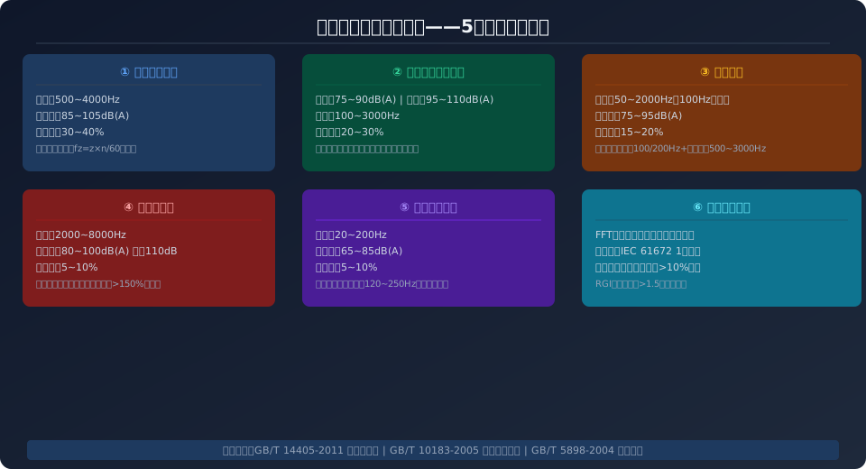
Five Noise Source Signatures in Bridge Travel Mechanisms
Based on vibration and noise spectrum data collected from 120 overhead crane service cases at Kelude, abnormal noise in the bridge travel mechanism can be classified into five source categories, each with distinct spectral characteristics and audible signatures. Maintenance personnel on site can perform initial fault localization without disassembling the mechanism by combining acoustic identification with instrument verification. Kelude recommends diagnosing each item in the following order during field troubleshooting.
Gear meshing noise—This is the dominant noise source in the travel mechanism, accounting for 30–40% of total noise. The meshing frequency is calculated using the formula fz=z×n/60 (where z is the number of teeth and n is the rotational speed in rpm), with a frequency range of 500–4,000 Hz and a sound pressure level of 85–105 dB(A). When gear teeth suffer from pitting, tooth breakage, or excessive backlash, prominent sidebands appear at the meshing frequency and its harmonics. Spur gears produce higher impact noise than helical gears; ground gears with Grade 6 accuracy run 3–5 dB(A) quieter than hobbed gears with Grade 8 accuracy.
Wheel–rail friction noise—Under normal operation, the sound pressure level ranges from 75–90 dB(A). However, when wheel rail gnawing occurs (forced friction between the wheel flange and the rail side), high-frequency screeching can surge to 95–110 dB(A), accounting for 20–30% of total noise and making it the most easily recognizable abnormal sound on site. Wheel rail gnawing is graded by rail gauge deviation per the FEM 1.001 standard for crane rail installation tolerances: ±3–5 mm is mild (occasional friction sounds), ±5–8 mm is moderate (continuous gnawing noise, address within one month), ±8–12 mm is severe (screeching plus monthly wear exceeding 2 mm), and beyond ±12 mm is critical (immediate shutdown required).
Motor noise—This includes electromagnetic noise (100 Hz fundamental plus 200 Hz harmonic, related to power supply frequency), mechanical noise (bearing rolling elements at 500–3,000 Hz), and ventilation noise (200–1,000 Hz), with a sound pressure level of 75–95 dB(A) and a contribution rate of 15–20%. Variable frequency motors produce the highest electromagnetic noise when operating in the 5–20 Hz low-frequency range. When bearings wear, high-frequency random broadband noise appears in the spectrum, which can be captured early using a dynamic acceleration sensor.
Brake noise—High-frequency pulse squeal generated by friction between the brake shoe and the brake wheel, with a frequency range of 2,000–8,000 Hz and a sound pressure level of 80–100 dB(A), with instantaneous peaks reaching 110 dB(A). Noise intensifies significantly when braking torque exceeds 150% of the rated value or when brake clearance falls below 0.5 mm. Per the ISO 4301 crane design standard, the safety factor for travel mechanism brakes must be ≥1.25.
Structural resonance noise—Resonance in thin-plate structures such as the main girder, end carriage, and walkway panels occurs in the 20–200 Hz low-frequency band, with sound pressure levels of 65–85 dB(A). Among these, walkway panels (steel plate thickness 3–5 mm) exhibit the highest resonance peaks in the 120–250 Hz band. Applying constrained-layer damping treatment (loss factor 0.35–0.60) can reduce resonance peaks by 10–15 dB(A).
Noise Spectrum Comparison Table for Five Fault Types
| Abnormal noise Type | Frequency Range(Hz) | Sound pressure leveld B(A) | Contribution Rate | Audible Characteristics |
|---|---|---|---|---|
| Gear Meshing | 500~4000 | 85~105 | 30~40% | Rhythmic"Humming"Sound, Varies with Rotational speed Variation |
| wheel track Friction | 100~3000 | 75~90 / Wheel rail gnawing / flange rubbing When95~110 | 20~30% | Periodic"Clicking"Sound, Wheel rail gnawing / flange rubbing High-Frequency Squeal |
| Motor | 50~2000 | 75~95 | 15~20% | Steady"Humming"Fundamental Frequency Tone, Bearing When Damaged"Rattling"Sound |
| Brake | 2000~8000 | 80~100(Peak110) | 5~10% | Harsh"Squeaking——"Sound, Braking Loudest Momentarily |
| Structural Resonance | 20~200 | 65~85 | 5~10% | Low-Pitched"Humming"Structural Resonance, Walkway / Platform Panel Vibration Sensation |
Abnormal Noise Diagnosis: A Step-by-Step Detection Guide
Troubleshooting abnormal noise from the crane bridge follows a three-tier diagnostic strategy: listen to locate, measure with instruments, then compare data. Execute the process systematically as outlined below:
Step 1: Zone-by-Zone Listening to Pinpoint the Source — Run the overhead crane at 50% of rated speed along the full length of the rail and back. A maintenance technician walks beneath the crane, using hearing to determine whether the noise originates from the left or right side of the bridge and which mechanism is involved (gearbox, wheel, motor, or brake). Simultaneously, observe the ammeter readings on both sides to check for an initial indication of uneven load distribution.
Step 2: Sound Pressure Level Measurement — Using an IEC 61672-1 Class 1 sound level meter, measure the A-weighted sound pressure level in two locations: inside the operator cab (at 1.2 m above the floor) and 1.5 m below the crane bridge. Acceptable levels are ≤85 dB(A) in the cab and ≤90 dB(A) below the crane. Record noise values under different operating conditions (empty travel and full-load travel in both directions) and compare them against historical data to identify any progressive deterioration.
Step 3: FFT Spectrum Analysis — Record the operating noise and perform a Fast Fourier Transform (FFT) spectrum analysis to identify the source of peaks by matching them against the frequency ranges of five common noise sources: gear meshing (500–4,000 Hz), wheel friction (100–3,000 Hz), motor electromagnetic noise (100/200 Hz), brake operation (2,000–8,000 Hz), and structural resonance (20–200 Hz). The presence of abnormal sidebands in the spectrum is a characteristic indicator of localized gear damage.
Step 4: Clamp Meter Current Deviation Check — Under both no-load and full-load conditions, use a clamp meter to measure the three-phase current of the bridge drive motors on both sides. A current deviation of <5% is considered normal; 5–10% indicates a minor concern (slight load imbalance); 10–15% warrants a warning (noticeable wheel rail gnawing); 15–25% is serious (requires immediate attention); and >25% is critical (single-side overload that could burn out the motor).
Step 5: RGI Comprehensive Wheel Rail Gnawing Index — Calculate the RGI using the formula: RGI = 0.30 × |ΔS|/5 + 0.25 × Wf/25 + 0.25 × Vr/0.5 + 0.20 × |ΔI|/10, where ΔS is the rail gauge deviation (mm), Wf is the wheel flange wear (mm), Vr is the rail side wear rate (mm/month), and ΔI is the current deviation (%). An RGI of <0.5 is normal, 0.5–1.0 requires attention, 1.0–1.5 is a warning, and >1.5 is severe and requires immediate shutdown. This index integrates the rail installation tolerance standards of FEM 1.001 with on-site maintenance data to provide a quantitative assessment of the severity of wheel rail gnawing.
Crane Rail Installation Accuracy: Inspection Standards and Tolerances
Rail installation accuracy is the leading cause of abnormal bridge travel noise, accounting for 35–40% of all wheel rail gnawing failures according to maintenance records. Routine inspections should verify rail geometry at the following frequencies and against the specified standards:
| Detection Item | Standard Requirement | Detection Tool | Detection Frequency |
|---|---|---|---|
| Track Gauge / Rail Gauge Deviation | ±5mm(≤30mSpan)/±8mm(>30m) | Steel Ruler/Laser Distance Sensor / Laser Rangefinder | Monthly |
| Crane Rail Straightness | ≤2mm/Full Length | Taut Wire Method/total station | Quarterly |
| Rail Elevation Deviation | ≤10mm(Same Cross-Section) | Level Instrument | Quarterly |
| Rail Joint Clearance | 2~4mm | Feeler Gauge | Monthly |
| Joint Height Difference/Misalignment | ≤1mm | Steel Plate Steel Ruler+Feeler Gauge | Monthly |
Common Abnormal Noise Causes and Remedial Actions
Below are the typical root causes for the five main categories of abnormal noise, along with the corresponding diagnostic methods and on-site corrective measures:
Gear Noise — Check the reducer oil level and condition (replace every 1,000 hours). Measure the backlash (normal range: 0.15–0.30 mm; if it exceeds 0.5 mm, adjustment or replacement is required). Replacing straight bevel gears with spiral bevel gears (helix angle 25°–35°) can reduce noise by 5–8 dB(A). Gear profile modification (tip relief of 5–15 μm) lowers impact noise by 2–3 dB(A). A reducer acoustic enclosure (2 mm steel plate + damping layer + sound-absorbing layer) provides a noise reduction of ≥20 dB(A).
Wheel Rail Gnawing Noise — For rail deviation issues, use the rail clamp adjustment method with stainless steel shims (0.5–2 mm) to realign the rail; after adjustment, straightness should be ≤2 mm per 40 m. For wheel deviation, when replacing the wheel block, ensure the coaxial outer diameter difference is ≤0.3 mm and the maximum difference across all four wheels is ≤0.5 mm. Horizontal guide rollers (diameter 200–300 mm, hardness HRC 50–55, clearance 3–5 mm) can reduce lateral forces by over 80%. For drive synchronization issues, use the VFD's auto-tuning function to ensure the speed difference between the two sides is ≤1%.
Motor Noise — Use a dynamic acceleration sensor (measuring range ±50 g, frequency response 0.5 Hz–10 kHz) to capture bearing vibration signals. A kurtosis value >3.5 indicates the bearing has entered the early stage of damage. Increasing the VFD carrier frequency from 2 kHz to 4–8 kHz can reduce electromagnetic noise by 3–5 dB(A), but the motor temperature rise must be evaluated. When replacing the flexible coupling, pay attention to shaft alignment accuracy (radial deviation ≤0.05 mm, angular deviation ≤0.05°).
Brake Noise — Adjust the brake clearance to 1.0–1.5 mm (noise increases sharply when clearance is <0.5 mm). Check the friction lining material — ceramic or copper-based powder metallurgy linings are 5–8 dB quieter than cast iron. Control the braking torque at 110–130% of the rated value (do not exceed 150%). A brake wheel surface roughness of Ra≤0.8 μm helps reduce friction squeal.
Structural Resonance — Apply constrained-layer damping materials to the walkway platform and main girder web plate (acrylic damping coating with η=0.10–0.25, reducing noise by 2–4 dB(A), or butyl rubber damping sheets with η=0.20–0.40, reducing noise by 3–5 dB(A)). Keep the resonance frequency away from the excitation frequencies of the travel mechanism (motor: 24 Hz, gears: 200–800 Hz, wheels: 2–8 Hz). Adjust the rib spacing of the walkway platform to shift the natural frequency. The troubleshooting methods above apply to the full range of Kelude overhead cranes (QD/QDX/LH types). Actual noise limits are based on the factory inspection report for each product.
Further Reading: Double-Girder Bridge Crane Wheel Rail Gnawing: Root Cause Analysis and Solutions — A systematic guide to diagnosing and resolving flange rubbing, the #1 cause of long travel noise.
Frequently Asked Questions
Q: I hear a periodic "clunk" during long travel. How do I tell if it's from the gears or the wheels?
A: Gear noise has a frequency that is proportional to rotational speed — it rises as the crane accelerates and falls as it decelerates, and you can feel vibration on the reducer housing. Wheel-related noise, on the other hand, is tied to the crane's position on the rail — it occurs each time the crane passes a specific rail joint or curve. In the frequency spectrum, gear noise peaks in the 500–4000 Hz range and shifts with speed, while wheel friction noise is broader, spanning 100–3000 Hz. Measuring the track gauge deviation (per FEM 1.001, tolerance ±5 mm) and inspecting wheel flange wear can help confirm the diagnosis.
Q: How is the severity of wheel rail gnawing quantified? At what RGI index must the crane be shut down immediately?
A: The severity is quantified using the comprehensive Rail Gnawing Index (RGI), calculated as 0.30×|ΔS|/5 + 0.25×Wf/25 + 0.25×Vr/0.5 + 0.20×|ΔI|/10. An RGI below 0.5 is considered normal (annual inspection); 0.5–1.0 requires attention (quarterly inspection); 1.0–1.5 is a warning (must be addressed within a month); and above 1.5 is severe — immediate shutdown is required. A typical combination of indicators for severe flange rubbing includes: track gauge deviation >12 mm + wheel flange wear >2 mm per month + rail side wear rate >2 mm per month + current deviation >25%. If any single parameter exceeds its critical threshold, the crane must also be shut down immediately for adjustment.
Q: If cabin noise exceeds 85 dB, which noise source should be addressed first?
A: Prioritize by contribution: gear meshing (30–40%), wheel-rail contact (20–30%), and motor (15–20%). First, measure the background noise inside the cabin with a sound level meter, then use an FFT spectrum analyzer to identify the dominant frequency peak. If the peak is in the 500–4000 Hz range, focus on the reducer first (switching to spiral bevel gears with ground teeth at Grade 6 accuracy can reduce noise by 5–8 dB). If the peak is in the 100–3000 Hz range and accompanied by a squeal, address the flange rubbing first (elastic wheels can reduce noise by 3–5 dB). Combining elastic wheels, damping coatings, and welded rail joints can achieve an overall noise reduction of 8–12 dB(A), meeting the FEM 1.001 limit.
Q: The noise disappeared after replacing the crane bridge wheels but returned after two months. What's the cause?
A: This usually indicates the root cause is not the wheels themselves but a systemic issue with the rail or the structure. If the new wheels show rapid flange wear again within 2–3 months, investigate in the following order: ① Use a total station to re-measure the rail straightness and track gauge (local out-of-tolerance conditions can cause continuous flange rubbing at specific positions); ② Check whether the main girder side bow exceeds L/2000 (often caused by prolonged overloading above 125% or eccentric loading, leading to bridge deformation); ③ Measure the current synchronization of the two motors during acceleration and deceleration (a speed difference >2% or braking torque difference >20% creates a yaw moment). If structural deformation is confirmed, flame straightening or the addition of horizontal guide rollers (clearance 3–5 mm, reducing lateral force by over 80%) is recommended.
