

Crane Brake Inspection Interval & Adjustment Standard
📋 Key Summary
The crane brake is a core component ensuring the safe operation of European Standard Double-Girder Cranes with capacities ranging from 50t to 300t. Inspection must strictly follow periodic standards; comprehensive clearance measurement is recommended every 15 days during routine inspections. Brake linings must be replaced immediately when wear reaches 50% of their original thickness. Scientifically adjusting braking torque and brake clearance effectively reduces load slipping risks under heavy loads, ensuring smooth braking for hoisting and travel mechanisms under full-load conditions to guarantee workshop logistics safety.
In crane design and maintenance systems, brake selection and adjustment must strictly adhere to relevant clauses in the FEM 1.001 Crane Design Specification. Simultaneously, daily safety supervision and periodic inspections must comply with the mandatory requirements of the TSG 51-2023 Safety Technical Supervision Regulation. As a manufacturer specializing in high-end customization within the B2B sector, Kelude Heavy Industry consistently emphasizes the importance of precise control over brake parameters in the maintenance system for 50t to 300t European Standard Double-Girder Cranes. The following analysis explores this topic across four dimensions: inspection intervals, engineering case studies, clearance adjustment, and system maintenance.
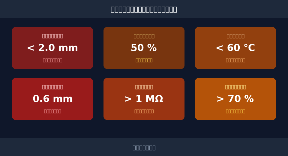
Daily Inspection Intervals and Core Parameter Requirements for European Standard Double-Girder Crane Brakes
For European Standard Double-Girder Cranes with capacities from 50t to 300t, brakes typically utilize block or disc structures. Daily inspection intervals should be differentiated based on Work Duty / Classification (e.g., A5, A6, A7). Under the standard A5 Work Duty / Classification, the wear amount on the brake wheel surface must not exceed 2mm. The initial thickness of the brake lining is typically 15mm; when friction material wears to 50% of its original thickness (i.e., 7.5mm remaining), new linings must be replaced. In A7 operating conditions characterized by frequent heavy-load braking, the inspection interval must be shortened by 30%.
During specific routine inspection operations, technicians must follow standardized procedures to ensure every key parameter meets design specification requirements. To facilitate execution by field personnel, we have broken down the inspection steps into the following independent stages:
Step 1: Inspect the surface condition of the brake wheel. The working surface of the brake wheel must be free of cracks. If grooves deeper than 2mm appear or wear reaches 2mm, turning repair or replacement is required. After turning, the reduction in brake wheel diameter must not exceed 3% of the original diameter.
Step 2: Measure brake lining wear. Use a vernier caliper to measure the remaining thickness of the friction material. When worn to 50% of the original thickness, new linings must be replaced. Additionally, check if lining rivets have sunk more than 2mm into the friction surface to prevent scratching the brake wheel.
Step 3: Verify the brake closure status. With power disconnected, the Brake Shoe should fullyContact the brake wheel. Check contact area using the dye method; the actual contact area must be no less than 70% of the theoretical contact area and must be evenly distributed.
Engineering Analysis of Braking Torque Calculation and Adjustment for Crane Brakes
Accurate calculation and adjustment of braking torque are core to ensuring safe crane braking. Taking the Crane Travel Mechanism of a 100t European Standard Double-Girder Crane produced by Kelude Heavy Industry as an example, we perform an engineering calculation for braking distance. Given that the rated operating speed of the Crane Bridge is 60m/min (converted to SI units as 1m/s), and the designed average deceleration is set at 0.5m/s², the total mass of the Crane Bridge (including Rated Lifting Capacity and Dead Weight) is approximately 180t.
According to kinematic formulas, braking distance s = v² / (2a). Substituting the values: s = 1² / (2 × 0.5) = 1 / 1 = 1m. This means that under a full load of 100t, the physical braking distance required for the Crane Bridge to come to a complete stop from 1m/s is 1m. During brake adjustment, the actual braking distance must be controlled between 0.8m and 1.2m to balance smooth braking with anti-slip requirements.
Regarding braking torque calculation, a safety factor must be considered. The calculation formula for the Braking torque Mz of the travel mechanism brake is: Mz = (Q + G) × v × η / (n × ω), where Q is the Rated Lifting Capacity of 100t, G is the Dead Weight of the trolley and lifting spreader, v is the Travel Speed, η is the transmission efficiency, n is the number of brakes, and ω is the angular velocity of the brake drum. Typically, the safety factor ranges from 1.5 to 2.0 to ensure reliable braking under extreme operating conditions. When adjusting the main spring, use a torque wrench to set the pre-tightening torque calculated above, keeping the error within ±5%.
Clearance Adjustment and Wear Compensation Standards for High-End Customized Crane Brakes (50t–300t)
For high-end customized cranes ranging from 50t to 300t, precise adjustment of brake clearance directly affects brake response time and smooth braking. It is generally required that the single-side clearance between the Brake Shoe and the brake wheel remains between 0.5mm and 1.0mm, with a recommended setting value of 0.6mm. Excessively small clearance leads to incomplete release, causing friction heat; excessively large clearance increases dead stroke, resulting in latency. Upon equipment delivery, Kelude Heavy Industry typically provides detailed guidance manuals for clearance adjustment, requiring maintenance personnel to use a feeler gauge for multi-point measurements.
The rated stroke of the hydraulic push rod is typically 40mm. During adjustment, ensure the release stroke is within the range of 10mm to 15mm to retain sufficient safety margin for wear compensation. Modern high-end brakes often feature wear compensation devices; when lining wear increases clearance, the compensation mechanism automatically adjusts the push rod stroke, eliminating the need for frequent manual intervention. However, after the compensation device acts 3 to 5 times, manual review of the baseline clearance is still required.
When adjusting Crane Bridge brakes, it is also necessary to evaluate the anti-collision safety distance based on workshop layout, ensuring that the braking distance plus safety margin does not cause equipment overshoot. Furthermore, for operating conditions with significant stress on the Main Girder, it is recommended to periodically synchronize weld crack detection to prevent structural fatigue caused by braking impact, ensuring the long-term safety of the entire metal structure.
Deep Maintenance of Hydraulic Thrust Brakes and Electrical Control Systems for Heavy-Load Crane Brakes
Under heavy-load, frequent braking operating conditions, the oil temperature of Hydraulic Thrust Brakes tends to rise. Standard requirements dictate that Hydraulic Oil working temperature must not exceed 60℃. If the Ambient Temperature is high, a cooling device must be installed. Technical engineers at Kelude Heavy Industry emphasize that hydraulic system maintenance concerns not only the brake itself but also the stability of the entire electrical control circuit. Regularly check Hydraulic Oil viscosity; if the oil emulsifies or turns black, replace it immediately and clean the internal filter screen of the Hydraulic Power Unit, which typically requires a filtration accuracy of 10μm.
Electrical Control & Maintenance Standards
For reliable electrical control, the Insulation Resistance of the Brake coil must exceed 1MΩ in a cold state, and operating voltage fluctuations should be kept within ±10% of the rated voltage. When using an AC contactor to control the brake, perform a Periodic Inspection for contact erosion; replace the Contactor immediately if the wear amount reaches 30% of its original thickness. Additionally, output voltage fluctuations exceeding 5% in the rectifier Module of the control circuit can cause improper engagement of the DC (Direct Current) Brake. Timely detection and replacement of these electronic components are essential.
In modern high-end crane systems, Braking start-stop control is often integrated with an anti-sway algorithm. By utilizing smooth Deceleration and acceleration curves, this setup minimizes Machinery mechanical shock, thereby extending the service life of the Brake. This electromechanical-hydraulic collaborative control requires maintenance personnel to possess not only mechanical adjustment skills but also the ability to read electrical parameters and analyze Fault codes, enabling effective Predictive Maintenance.
| cranecapacityRange | routine inspectionCycle | Overhaul Interval | Coreinspection itemAndParameterStandard |
|---|---|---|---|
| 50t - 100t | Per 15 Day(s) | Per 6 Month(s) | Liningwear amount ≤50%、Single-side Clearance 0.5~1.0mm |
| 100t - 200t | Per 10 Day(s) | Per 4 Month(s) | LiningWear、hydraulic push rodstroke 10~15mm、pinLubrication |
| 200t - 300t | Per 7 Day(s) | Per 3 Month(s) | LiningWear、hydraulic systemoil temperature ≤60℃、Braking torqueTesting |
| fault symptomDescription | possible causeAnalysis | On-sitetroubleshooting methods | Long-termPreventive Action |
|---|---|---|---|
| BrakingCauses Severe ... Duringvibration | Brake wheelSurface Has Oil Stains orWearUneven | Clean Oil Stains,TurningOrreplacementBrake wheel | Regularly Clean,Keep Surface Clean |
| Friction Noise Upon Brake Release | Brake shoeClearance Too Small or Uneven on Both Sides | Re-adjustmentAdjust Clearance to 0.6mm characteristic value | After Each MaintenancerecheckClearance Data |
| hydraulic push rodInsufficient Thrust | Low Fluid Viscosity or Internal Leakage | replacementSpecified GradeHydraulic Oil,RepairSealing | Monitoringoil temperature,RegularlyreplacementHydraulic Oil |
| BrakeUnable to Close Completely | SpringFatigueDeformationOr Mainspring fracture | replacementSameSpecificationNewSpring,Re-Calibration | periodic testingSpringElastic ForceattenuationRate |
Frequently Asked Questions
Q: At what wear thickness must brake linings be replaced?
A: Replacement criteria are based on the percentage of material loss rather than a fixed millimeter value. Linings must be replaced when the friction material wears down to 50% of its original thickness. For instance, if the initial thickness is 15mm, replacement is mandatory once the remaining thickness reaches 7.5mm to prevent braking failure.
Q: How do I adjust excessive braking distance in the Crane Travel Mechanism?
A: Excessive braking distance typically results from insufficient Braking torque or excessive clearance. First, inspect and clean oil stains from the Brake wheel surface. Second, adjust the Brake shoe gap to the standard range of 0.5mm to 1.0mm. Finally, increase the Braking torque by compressing the main spring until the braking distance meets design specification requirements.
Q: What corrective measures should be taken for high hydraulic push rod oil temperature?
A: Hydraulic Oil temperatures exceeding 60°C (140°F) can cause Seal aging and reduced thrust. Corrective measures include inspecting and replacing Hydraulic Oil with the correct viscosity, cleaning dust from the radiator surfaces, and installing Forced Air Cooling or water-cooling systems for the Hydraulic Power Unit if Ambient Temperature remains consistently high. This ensures the oil temperature stays within safe operating limits.
Q: How do I troubleshoot Load slipping in the Hoisting mechanism brakes?
A: Load slipping is a critical safety hazard. Troubleshooting steps include: checking if worn Brake Lining has reduced the friction coefficient; inspecting whether the main Spring has fatigued, resulting in insufficient clamping force; and verifying that the Brake wheel surface is free of oil contamination that lowers Friction Force. After identifying the root cause, replace damaged components and recalibrate the Braking torque.
