

How to Set Crane Anti-Collision Safety Distance
📋 Key Summary
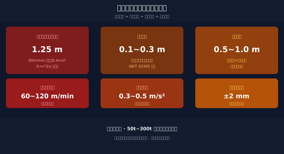
When multiple cranes share the same rail, the anti-collision safety distance is a safety boundary that must be quantified. It is the sum of three components: braking distance, buffer distance, and safety margin. Braking distance is the dominant term, equal to the square of travel speed divided by twice the braking deceleration. This article provides the complete calculation path along with a verification example, and explains the graded braking logic for multi-crane avoidance—tightening step by step from the deceleration zone to the stop zone, so that every approach has a defined numerical limit rather than relying on the operator's eyesight and luck.
Two overhead cranes traveling toward each other on the same rail—neither operator can clearly see where the other's suspended load is hanging. By the time you spot the other crane's chassis frame from the operator cabin, you often have only one or two seconds left to brake. In steel mills, shipyards, and large warehousing workshops, this scenario plays out almost every day.
At most plants, anti-collision devices are installed and their distances set by gut feeling—some use two limit switches as an anti-collision solution, others set the laser rangefinder alarm distance to a number pulled out of thin air. The real problem is that safety distance can be calculated, yet few people bother to do the math.
This article breaks down that calculation. When Kelude Heavy Industry carries out intelligent upgrading for multiple overhead cranes on the same rail, the first step is always to work out the safety distance figures before deciding which sensors to install or what avoidance logic to use.
Why Multi-Crane Safety Distance Must Be Quantified
In steel mill raw material bays, finished product bays, shipyard block storage yards, and large warehousing workshops, it is common for two or more overhead cranes to share the same rail. A crane-to-crane collision can range from damaged end carriages, buffers, and steel structure to a dropped load injuring ground personnel. To upgrade anti-collision from "gut feeling" to "numbers," you must first define three boundary conditions.
The first boundary condition is travel speed. The Crane Travel Mechanism of a bridge crane typically operates at 20–120 m/min, with medium-to-large overhead cranes commonly running at 60–90 m/min. This figure directly determines the order of magnitude of the braking distance.
The second boundary condition is braking deceleration. It is determined jointly by the Brake's Braking torque and the inertia of the crane travel mechanism. In engineering practice, 0.3–0.5 m/s² is typically used. Too low a value extends the braking distance; too high a value causes braking impact and load swing.
The third boundary condition is detection and response. From the moment the Anti-Collision Device detects a target to the moment it issues a braking command, there is latency from sensor sampling, communication transmission, and mechanism actuation. This latency multiplied by travel speed is part of the safety margin that must be reserved.
These boundary conditions are addressed in ISO 23812:2021 "Intelligent Anti-Collision Systems for Cranes" and ISO 12480-1 "Safety Regulations for Lifting Appliances"—the former specifies the functions and performance of intelligent anti-collision systems, while the latter mandates the installation of anti-collision devices as safety protection devices.
Safety Distance Formula: Braking, Buffer, and Margin
The anti-collision safety distance is not a single arbitrary number—it is the sum of three parts: braking distance, buffer distance, and safety margin. Their magnitudes and calculation methods are entirely different, and conflating them is the root cause of most on-site misjudgments.
Braking distance is the dominant term. It is given by the classic uniform deceleration formula: S = v²/2a, where v is the travel speed (in m/s) and a is the braking deceleration (in m/s²). Watch the units—when someone says "60 m/min" on site, you must divide by 60 to convert to m/s before plugging it into the formula. Get this step wrong and the distance will be off by orders of magnitude.
Buffer distance corresponds to the stroke of the buffer. The polyurethane (PU) or Hydraulic buffer mounted on the crane's end carriage absorbs impact energy through compression at the moment of collision. This stroke is typically 0.1–0.3 m. For buffer selection, refer to ISO 10245 "Buffers for Cranes".
The safety margin is the final safeguard, covering sensor detection error, communication latency, mechanism actuation latency, and operator reaction time. It is not calculated but estimated based on the operating condition, typically 0.5–1.0 m in engineering practice. FEM 1.001 "Crane Design Specification" sets clear requirements for the braking performance of the crane travel mechanism, and the braking deceleration value should be consistent with it.
Verification Example at 60 m/min Travel Speed
Below is a complete verification using the most common travel speed of 60 m/min. Convert 60 m/min to 1.0 m/s, take a braking deceleration of 0.4 m/s², and plug into S = v²/2a to calculate the braking distance.
Braking distance = 1.0² ÷ (2 × 0.4) = 1.25 m. Taking a buffer distance of 0.2 m and a safety margin of 0.8 m, the three terms sum to an anti-collision safety distance of approximately 2.25 m for this crane.
This 2.25 m means: when the gap between two cranes narrows to within 2.25 m, even immediate braking cannot stop them before contact. Therefore, the alarm distance of the anti-collision device must be greater than 2.25 m. In actual engineering, it is usually enlarged to 3 m or more to leave room.
Kelude Heavy Industry calculates each speed step individually during project verification, then compiles the results into a table for on-site commissioning personnel to avoid estimating distances by experience. The braking distance comparison across different speed steps is shown below.
| travel speed(m/min) | Conversionspeed(m/s) | braking deceleration(m/s²) | braking distance(m) |
|---|---|---|---|
| 20 | 0.33 | 0.40 | 0.14 |
| 40 | 0.67 | 0.40 | 0.56 |
| 60 | 1.00 | 0.40 | 1.25 |
| 90 | 1.50 | 0.40 | 2.81 |
| 100 | 1.67 | 0.40 | 3.47 |
| 120 | 2.00 | 0.40 | 5.00 |
| 150 | 2.50 | 0.40 | 7.81 |
Graded Braking Logic for Multi-Crane Avoidance: Deceleration, Stop, and Priority Zones
Once the safety distance for a single overhead crane is established, multi-crane avoidance requires an additional layer of logic—graded braking. The distance between two cranes is divided into three zones based on the safety distance, so that the closer the cranes get, the more aggressive the response, avoiding the shock of an immediate emergency stop.
Level 1 is the deceleration zone: when the gap exceeds twice the safety distance, normal operation continues.
Level 2 is the deceleration zone: when the gap narrows to between one and two times the safety distance, Crane Bridge travel speed is reduced to 50% of rated capacity.
Level 3 is the stop zone: when the gap falls below the safety distance, Braking and shutdown occur immediately.
Avoidance priority must also be predefined. Loaded cranes take priority over No-load cranes, cranes ahead in the same direction have right of way, and cranes on intersecting bays yield according to the main-bay priority principle. Once this priority scheme is written into the PLC program, anti-collision no longer depends on the operator's judgment in the moment.
the technical director pointed out: "Calculating the safety distance is only the first step. The real challenge is writing the graded braking thresholds and priority rules into the PLC program, so the crane holds that line even without human intervention."
GB/T 28264 Safety Monitoring and Management System requires real-time monitoring and recording of safety states such as anti-collision. The avoidance action data of multiple cranes is also retained by the system as a basis for post-event traceability.
Kelude Heavy Industry's retrofit solution integrates the graded braking thresholds and priority rules with the monitoring system, enabling multiple cranes on the same Crane Rail to avoid each other in an orderly manner without human intervention. The corresponding safety distances at each speed level are summarized below.
| speedGear Position(m/min) | braking distance(m) | Bufferdistance+safety margin(m) | safety distanceTotal(m) |
|---|---|---|---|
| 40 | 0.56 | 1.0 | 1.56 |
| 60 | 1.25 | 1.0 | 2.25 |
| 90 | 2.81 | 1.0 | 3.81 |
| 120 | 5.00 | 1.0 | 6.00 |
📖 Related reading: Explosion-Proof Crane Selection: Matching Explosion Protection Class to the Operating Environment | Three-in-One vs. Split-Type Gearbox: Maintenance Cost Differences and Selection Criteria
FAQ
Q: Where are the detection blind spots for laser distance measurement versus encoder-based anti-collision systems?
A: Laser distance measurement delivers accuracy down to ±2mm, but dust, rain, fog, and direct strong light can cause dropped frames. Encoder positioning holds roughly ±5mm accuracy and is unaffected by weather, but it only tracks the crane's own position—it cannot directly sense an oncoming overhead crane. The two are often used in conjunction: the encoder provides precise coordinates while the laser performs close-range verification.
Q: What safety margin is typically applied to the anti-collision safety distance, and is there a standard to reference?
A: Braking distance is calculated by formula, while the safety margin must cover detection error, communication latency, and operator reaction time—in practice, 0.5–1.0m is common. A response time of 0.2s multiplied by a travel speed of 1.0m/s gives 0.2m, to which detection error and a conservative coefficient are added. The Anti-Collision Device must reliably actuate within the danger distance; exact values are subject to on-site measurement.
Q: How much does it cost to retrofit a 20t overhead crane with a complete anti-collision system?
A: A single laser distance measurement anti-collision device plus installation and commissioning typically runs about $1,500 to $3,000. An avoidance system linking multiple overhead cranes on the same rail involves communication networking and PLC programming, so the investment is higher. Kelude's retrofit quotations are calculated based on the actual operating condition, number of rails, and required functions—subject to the actual contract.
Q: Can Kelude provide a complete anti-collision retrofit package for multiple overhead cranes on the same rail?
A: When there are few cranes and speeds are low, laser distance measurement with graded braking can be used first. For multi-crane coordination with automatic avoidance, encoder positioning plus wireless communication networking is required. Kelude supplies supporting anti-collision and intelligent upgrading solutions for 50t–300t European-standard double-girder cranes, customized to the on-site operating condition.
