

Crane AI: Smarter Isn't Pricier
📋 Key Summary
When retrofitting a crane with intelligent controls, the hidden cost of choosing the wrong algorithm usually outweighs the price difference between the algorithms themselves. The problem is rarely that an algorithm isn't advanced enough — it's that the control objectives don't match the operating conditions. This article focuses on anti-sway control for European-standard double-girder cranes, comparing the control principles, application boundaries, and life cycle costs of three mainstream approaches: PID closed-loop control, fuzzy logic control, and model predictive control. It lays out a decision framework for selecting an algorithm based on three dimensions: lifting capacity, travel speed, and takt time. The real measure of an algorithm isn't its complexity — it's whether three indicators (residual sway angle, positioning accuracy, and response time) can consistently meet process requirements.
In most automation project technical agreements, the targets for crane anti-sway control are written as "residual sway angle not exceeding 0.3° and positioning accuracy of ±5 mm." These two figures set the threshold for algorithm selection. The tighter the sway angle requirement, the more you need an algorithm capable of handling strong nonlinearity and multiple constraints. Positioning accuracy, meanwhile, depends heavily on how well the algorithm coordinates with sensing components such as encoders and Gray-code bus positioning systems.
But a higher threshold doesn't mean a more expensive algorithm is always the answer. In real projects, a 20 t medium-speed overhead crane can reliably hit the same 0.3° residual sway target using classic PID with feedforward compensation. Switch to a 100 t European-standard double-girder crane running at high speed over long distances, and PID's fixed parameters clearly struggle when the load's swing period changes with rope length. Algorithm selection is fundamentally about aligning control objectives with operating conditions — not about stacking up computing power.
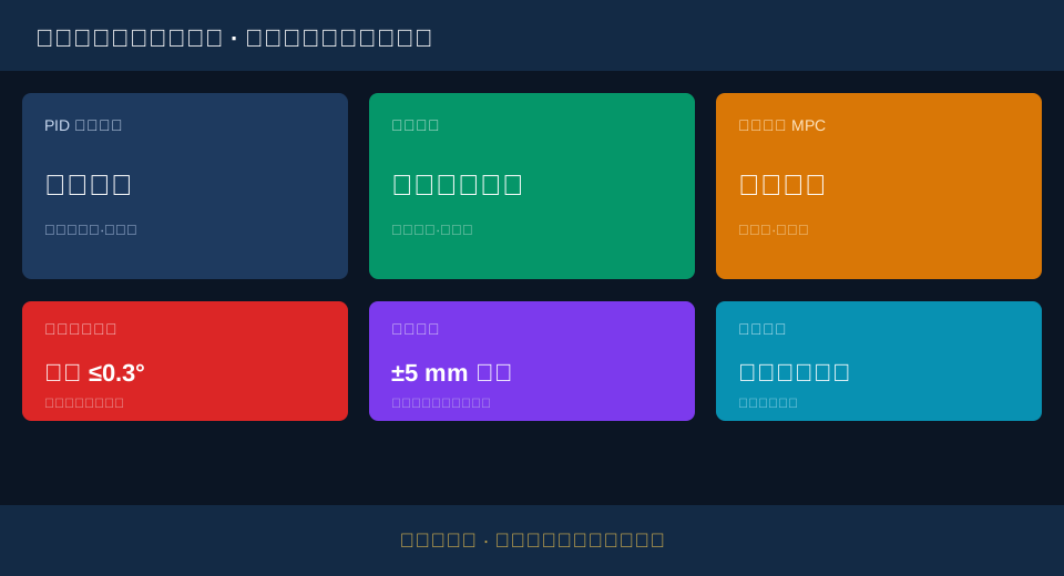
Anti-Sway Algorithm Types: PID, Fuzzy Logic, and MPC Compared
Anti-sway control is essentially about making the load's swing converge to an acceptable range before reaching the target position. The three mainstream algorithms differ in how they describe and predict this swing process.
PID closed-loop control treats the sway angle as a deviation and continuously corrects the trolley speed setpoint through proportional, integral, and derivative terms. It's structurally simple, has few parameters, and is by far the most widely deployed type in service today. Its weakness is that parameter tuning depends on operating conditions — change the rope length or load, and the optimal parameters drift.
Fuzzy logic control doesn't rely on a precise mathematical model. Instead, it encodes an experienced operator's instincts — "slow down when it swings hard, brake early when approaching the target" — into a rule base, using membership functions to handle strongly nonlinear problems like load sway. It's robust against disturbances, but the completeness of the rule base determines its control ceiling.
Model predictive control (MPC) solves a constrained optimization problem at every cycle, factoring in the sway trajectory several steps ahead. It offers the highest accuracy and can explicitly handle physical constraints on speed and acceleration — at the cost of high computing power demands and stricter real-time performance requirements for the controller.
Regardless of which algorithm is used, the controller hardware and safety circuit must meet the general requirements for electrical control equipment set out in ISO 10245, "Electrical Control Equipment for Cranes". Algorithm implementation cannot operate outside the safety boundaries of the electrical system. The real difficulty is that the on-paper performance differences among the three algorithms often get amplified or erased by operating condition parameters once they hit a specific project.
Core Parameters Compared: Residual Sway, Positioning Accuracy, and Response Time
Selection isn't about the algorithm's name — it's about what indicators it can reliably deliver under the target operating conditions. The parameter matrix below provides a side-by-side comparison of the three algorithms at typical operating magnitudes.
| Algorithm Category | Residualsway angleTypical Value | Steady StatePositioning Accuracy | StepResponse time | Disturbance Rejection Capability | Controllercomputing powerrequirements |
|---|---|---|---|---|---|
| PID closed loop | ±1.0°~±0.5° | ±10 mm Order of Magnitude | Medium | Moderate,ParameterDrift | Low |
| Fuzzy Logic Control | ±0.5°~±0.3° | ±8 mm Order of Magnitude | Relatively Fast | Strong | Medium |
| Model Predictive MPC | ≤±0.3° | ±5 mm Within | Relatively Fast | Strong,Explicit Constraints | High |
| Gaindispatching PID | ±0.4°~±0.2° | ±6 mm Order of Magnitude | Relatively Fast | Relatively Strong | Medium-High |
| Industry CommonAcceptanceLine | ≤0.3° | ±5 mm | — | — | — |
The values in the table represent typical ranges under standard operating conditions. Target values for any specific project are governed by the Technical Agreement and the signed contract. Lab data and field data often diverge by around 20%, because the combination of rope length, wind speed, and load weight on site is far more complex than any simulation.
One additional point deserves attention: the safety function itself. Anti-sway control is a safety-related function of the Electrical Control System, and its hardware and software must be designed and validated in accordance with the functional safety level requirements of IEC 62061, Safety of machinery — Functional safety of electrical control systems. Do not focus solely on performance indicators while overlooking safety integrity.
Which Anti-Sway Algorithm Fits Your Operating Condition?
Here is a three-step decision chain for algorithm selection. Follow these steps and most projects will avoid the trap of paying a premium for precision they will never use.
Step 1: Lifting Capacity and Rope Length Variation. The heavier the load and the more frequently rope length changes, the more the swing period shifts — and the worse a fixed-parameter algorithm performs.
Step 2: Travel Speed and Start-Stop Frequency. High-speed, high-takt-time operations demand faster convergence and better real-time performance. A simple PID with fixed gains struggles to cover the full range.
Step 3: Positioning Accuracy Combined with Takt Time. Only projects that require high positioning accuracy and tight takt times justify the computing power and commissioning cost of MPC.
📋
PID Closed-Loop
Best for medium-to-low speed, stable rope length
📋
Fuzzy Logic Control
Strong nonlinearity, disturbance rejection
📋
MPC Model Predictive
High accuracy, high takt time, heavy load
📋
Gain-Scheduled PID
Balances cost and adaptability
📋
Anti-Sway + Positioning
Unified sway and alignment control
📋
Safety Circuit Redundancy
Functional safety level matching
📋
Sensor Co-Selection
Encoder and Gray-code bus pairing
📋
Life Cycle Cost
Includes commissioning, maintenance, upgrades
On the cost side, calculate the total cost — not just the hardware unit price. The table below compares the three approaches across cost, commissioning, and maintenance at an order-of-magnitude level.
I don't see any Chinese HTML source content in your message — the "【Original Text】" section is empty. Please paste the Chinese HTML you'd like me to localize into English, and I'll return the translated HTML with all tags, attributes, Gutenberg comments, and placeholders preserved exactly as specified.| Solution | hardware costOrder of Magnitude | CommissioningCycle | maintenanceComplexity |
|---|---|---|---|
| PID closed loop | Low | Short | Low,ButParameterRequiresperiodic review |
| Fuzzy Logic Control | Medium | Medium | Medium,Rule Base Requiredmaintenance |
| Model Predictive MPC | High | Long | High,Model Requires Continuous Correction |
| integrated solution | subject to the actual contract | Depends on Range | Depends on System Complexity |
As the technical director at Kelude Heavy Industry pointed out: "The biggest risk in algorithm selection is trying to force a one-size-fits-all solution onto every project. On European-standard double-girder crane projects, we start by pulling the rope length, load capacity, and takt time data for the target operating conditions, then match the algorithm to that data — not the other way around, where the operating conditions are bent to fit the algorithm."
The overall safety requirements for the Electrical Control System should also reference the relevant provisions of ISO 24617:2020, Safety Requirements for Crane Electrical Control Systems, evaluating algorithm performance and electrical safety on the same chart. Specific configurations are subject to the actual contract.
📖 Related reading: Retrofit Path and Cost Boundaries for Upgrading Bridge Crane Relay Control to PLC with VFD | Maintenance Cost Differences and Selection Basis: Three-in-One Gearbox vs. Traditional Split-Type Gearbox
FAQ
Q: How much does PID differ from model predictive control in residual sway angle, and when is MPC absolutely necessary?
A: Under typical operating conditions, PID leaves a residual sway angle of ±1.0° to ±0.5°, while MPC can hold it within ±0.3°. MPC becomes necessary when loads are heavy, rope length changes frequently, positioning accuracy must be within ±5 mm, and takt time is tight — situations where fixed-parameter PID struggles to perform across the full range. For small-to-medium capacity, low-to-medium speed applications, PID with feedforward compensation is often the more cost-effective choice.
Q: What residual sway angle and positioning accuracy count as meeting the standard for anti-sway algorithms, and how should acceptance criteria be defined?
A: Most automation projects specify "residual sway angle not exceeding 0.3° and positioning accuracy of ±5 mm" in the Technical Agreement as the acceptance threshold. More demanding metallurgical or precision assembly applications may require ±3 mm or tighter. The specific target values are subject to the project's Technical Agreement, and acceptance testing should measure multiple points across the full travel rather than a single point.
Q: Roughly how much does it cost to retrofit an existing crane with an anti-sway control system?
A: Cost depends on lifting capacity, controller grade, sensor configuration, and commissioning scope — the range is wide, and there is no uniform unit price. Hardware cost spans from the low end of a PID solution to the high end of an MPC solution, with integration and commissioning billed separately. Every Kelude Heavy Industry project is calculated unit by unit based on actual operating conditions, and the final quotation is subject to the actual contract.
Q: How do you tell whether the current anti-sway algorithm selection truly matches the operating conditions?
A: Watch for three signals: whether residual sway angle fluctuates by more than 50% across different loads with the same parameter set; whether control performance clearly degrades between high-speed and low-speed ranges; and whether manual fine-tuning is still needed during positioning. If any one of these appears, the algorithm no longer matches the operating conditions and the selection needs to be re-verified.
Kelude Heavy Industry specializes in high-end customization of 50t–300t European-standard double-girder cranes. Anti-sway and positioning control solutions are verified unit by unit against project operating conditions, with indicators such as residual sway angle and positioning accuracy documented in verifiable acceptance documents. Specific configurations are subject to the actual contract.
