

Crane Remote Control Selection: 4 Key Factors & Installation
Industrial wireless remote controls are the core devices for remote operation of bridge and gantry cranes. Selection should weigh four key factors: frequency band (433MHz/2.4GHz), safety level (PL d/SIL 2), control capacity (8–32 relay outputs), and environmental protection (IP65/-25–70°C). During installation, the antenna must be oriented vertically upward and kept at least 0.5m away from the VFD.
Industrial wireless remote controls are essential operating devices for bridge and gantry cranes, allowing operators to work from outside the hazardous area beneath the suspended load and significantly reducing safety risks. A compliant crane remote control system must meet the functional safety and reliability requirements for control devices set forth in ISO 4301 Crane Design Standard and TSG 51-2023 Crane Safety Technical Supervision Regulation. This article provides a systematic reference for engineering selection and on-site installation, covering frequency band selection, safety levels, control capacity, environmental protection, receiver mounting requirements, and the pairing and commissioning procedure.
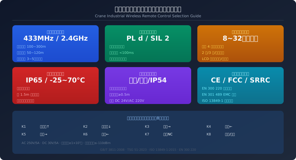
Frequency Band Selection and Communication Range
The two most common frequency bands for industrial wireless remote controls are 433MHz and 2.4GHz, each suited to different application scenarios. The 433MHz band is an ISM license-free band with a wavelength of approximately 0.69m. Its strong diffraction capability maintains a reliable communication link even after penetrating three to five layers of steel structure. In open areas, the line-of-sight communication range reaches 300m, while in a typical industrial workshop the effective coverage is approximately 50–120m. Transmit power is typically limited to 10mW (per China's SRRC certification requirements), with GFSK or LoRa spread-spectrum modulation used for interference-resistant communication.
The 2.4GHz band is also a globally available ISM band with a wavelength of about 0.125m and abundant bandwidth resources. 2.4GHz remote controls support frequency-hopping spread spectrum (FHSS) technology, rapidly switching across 79 channels for excellent narrowband interference rejection. Open-area communication range is approximately 100–200m, but penetration through steel structures is weaker than 433MHz — signal attenuation after passing through two layers of steel plate is roughly 15–20dB. The 2.4GHz band is well suited to workshops with complex electromagnetic environments and multiple units operating simultaneously; FHSS+DSSS hybrid spread spectrum reduces the probability of co-channel interference to below 0.1%. As a general guideline, 433MHz is recommended for large steel structure workshops and outdoor gantry cranes, while 2.4GHz suits small-to-medium workshops and multi-crane coordination scenarios.
Safety Level and Redundant Design
The safety level of a crane remote control must comply with PL d (Performance Level d) per ISO 13849-1:2015 or SIL 2 (Safety Integrity Level 2) per IEC 62061. Both levels require a probability of dangerous failure per hour (PFHd) of less than 1×10⁻⁶. To meet this requirement, the remote control must adopt a dual-channel redundant architecture — the transmitter and receiver each incorporate two independent microcontrollers (MCUs) that cross-check every control command. If either channel detects a data mismatch, a safety shutdown is triggered immediately.
The emergency stop button is the core safety component of the remote control system, with a response time not exceeding 100ms. Per TSG 51-2023, the emergency stop circuit must be hard-wired — it must not pass through any programmable electronic system — ensuring reliable power disconnection even in the event of a software failure. Additionally, the remote control must include a "lost-link protection" function: if the receiver fails to receive a valid heartbeat signal from the transmitter for three consecutive communication cycles (typically 150ms), it automatically shuts down and latches the fault state, requiring a manual reset before restart. For cranes rated for heavy-duty or very heavy-duty classifications, receivers with independent safety relay outputs are recommended, physically isolating emergency stop and limit signals from standard control signals.
Control Capacity and Functional Configuration
The number of control channels on a crane remote control depends on the complexity of the crane mechanisms. For a standard bridge crane (long travel + cross travel + main hoist), at least 6 relay outputs are required (one forward and one reverse per mechanism × 3 mechanisms). Adding auxiliary hoist, grab open/close, or lifting magnet functions increases the requirement to 8–12 outputs. Large ladle cranes with main and auxiliary hoists, trolley rotation, and bridge skew correction may need 16–32 outputs. Each relay contact should be rated at AC 250V/5A or DC 30V/5A, with a mechanical life of ≥1×10⁷ cycles.
For speed control, entry-level and mid-range remote controls offer 2-step stepped control (fast/slow) using two relay outputs in conjunction with pole-changing motor windings. Higher-end models support 3-step or stepless control, using analog output (0–10V or 4–20mA) to directly command the VFD frequency reference for smooth acceleration and precise positioning. Some smart remote controls feature an LCD display screen that shows transmitter battery level, receiver operating status, fault codes, and received signal strength indication (RSSI), helping operators assess communication quality and equipment health in real time. At minimum, a 3-step speed control function is recommended to support both fine positioning at close range and rapid travel over longer distances.
433MHz vs 2.4GHz: Engineering Comparison for Industrial Remote Controls
The following comparison evaluates both frequency bands across four key engineering criteria: communication range, wall penetration capability, interference resistance, and application scenarios.
| Comparison Item | 433MHz | 2.4GHz | Selection Recommendation |
|---|---|---|---|
| Communication Range(Open Area) | 100~300m | 100~200m | Heavy-Duty Gantry Crane Recommended433MHz |
| Penetrationsteel structure Capability | High, Penetration3~5Floor | Low, Penetration1~2Floor | Multi-Story Steel Structure Workshop Recommended433MHz |
| Data Transmission Rate | ≤200kbps | ≤2Mbps | Both Suitable for Simple On/Off Control |
| Co-Channel Interference Rejection | Fair, Fixing Channel | Excellent, FHSSFrequency Hopping | Recommended for Dense Multi-Unit Operation2.4GHz |
| Antenna Size | Approx.17cm(1/4Wavelength) | Approx.3cm(1/4Wavelength) | receiver For Space-Constrained Applications2.4GHz |
| SRRCCertification Complexity | Low, Single Channel Testing | Medium, Hopping Sequence Testing | Domestic Projects433MHzCertification Shorter Lead Time |
| Kelude Recommended | Heavy-Duty/Outdoor/steel structure | Light-to-Medium Duty/Multi-Unit/Clean Environment | Select Based on Actual Operating Conditions |
Receiver Installation Position & Parameter Checklist
Before installation, verify each parameter against the checklist below to prevent communication dropouts or unintended equipment operation caused by improper setup:
| Inspection Item | Standard Requirement | Detection Method | Non-Conformance Action |
|---|---|---|---|
| Antenna Perpendicularity | Deviation≤5° | Measure Antenna Mast with Spirit Level | Air Compressormounting bracket Angle |
| Antenna-to-Metal Clearance | ≥50cm | Measure to Nearest Metal Surface with Tape Measure | Extend Antenna Mounting Mast |
| Distance From Frequency Inverter / VFDCommunication Range | ≥0.5m | Measure Center-to-Center Distance with Tape Measure | Add Metal Diaphragmor Relocate |
| Power Supply Voltage | DC 24V±10%or AC 220V±15% | multimeter Measure at Input Terminals | Air Compressor Transformer Tap |
| E-Stop Circuit Wiring | NCContact+Dedicated Terminal | Continuity Testing+Visual Inspection | Rewire per Diagram |
| Shield Grounding | receiver Single-Ended (One Side)Grounding | multimeter Measure Shield-to-Ground | Disconnect PLCSide Grounding |
| Kelude Acceptance Standard | Successful Pairing After Power-Up+E-Stop Testing Pass | 50mCommunication Range3E-Stop Cycles Testing | Troubleshoot Antenna/Power Supply/Co-Channel Interference Rejection |
Receiver Installation Best Practices and Wiring Guidelines
The quality of receiver installation directly affects the communication reliability and service life of the remote control system. The receiver enclosure should have a protection rating of at least IP54 and be mounted on a dedicated mounting plate on top of the crane electrical cabinet or on the walkway/platform. The antenna must be installed pointing vertically upward, with no large metal obstructions (such as cabinet side panels or cable trays) within a 50 cm radius. For optimal omnidirectional radiation characteristics, the antenna tip should extend at least 20 cm above the top edge of the cabinet. The distance between the receiver and the frequency inverter (VFD) should be ≥ 0.5 m; if this clearance cannot be achieved, a metal diaphragm must be installed between them for electromagnetic shielding.
Two common power supply options are available:
① AC 220V direct supply — Power is taken from the secondary side of the crane control transformer and converted to DC voltage via the receiver's internal rectification and voltage stabilization module. This option suits retrofits of older cranes with traditional relay-contactor control systems.
② DC 24V supply — Power is drawn from a switching power supply module, providing stable voltage with low ripple. This option is ideal for PLC-controlled cranes. A fast-acting fuse (rated at 80% of the contact capacity) should be connected in series between the relay output terminals and the contactor coil or PLC input points to prevent load short circuits from burning out relay contacts. All signal cables should use 0.5–1.0 mm² copper-core shielded wire, with the shield single-point grounded at the receiver side to avoid ground loops that introduce interference.
Pairing, Commissioning, and Functional Testing
After installing a new remote control or replacing an existing one, the transmitter and receiver must be paired (bound) before use. While the pairing procedure varies slightly between brands, the core process is consistent — place the receiver into pairing mode (typically via DIP switches or shorting dedicated terminals), then press the pairing button on the transmitter (usually a combination of keys). The receiver writes the transmitter's unique ID into its internal EEPROM upon receiving the pairing request. After successful pairing, the receiver status indicator should change from fast flashing to steady on or slow flashing, confirming the pairing relationship. A single receiver can typically pair with 2–4 transmitters (for master/slave operation or multi-controller scenarios), but only one transmitter can be in active control at any given time.
Once pairing is complete, functional and safety tests must be performed. Functional testing verifies each mechanism individually: within a 50 m range, operate the hoist up/down, trolley left/right, and crane forward/reverse to confirm correct direction of movement and no response delay. Safety testing focuses on the following key points:
① Pressing the emergency stop button must immediately halt all mechanisms (use an oscilloscope to verify relay contact opening time ≤ 100 ms).
② When the transmitter is powered off or moves out of communication range, the receiver must automatically trigger a shutdown within 150 ms.
③ Dual-channel cross-check — artificially cutting power to one of the MCUs must prevent the system from outputting any control signals. After all tests pass, record the commissioning results and archive them for future reference as part of the equipment acceptance documentation.
Troubleshooting Common Remote Control Faults
During operation, remote control systems may experience communication interruptions, unintended actuation, or reduced control range. The most common cause of communication interruption is a loose antenna or a broken antenna cable — use a network analyzer to measure the VSWR (Voltage Standing Wave Ratio) at the antenna port. Normal values should be ≤ 1.5; readings above 2.0 indicate an open or short circuit in the antenna or feed line. Another frequent cause is co-channel interference, characterized by the communication range suddenly dropping from 100 m to under 10 m while short-range operation remains normal. In such cases, check for other wireless devices operating in the same frequency band (e.g., 433 MHz access control systems, two-way radios, TPMS sensors), switch to an unused channel, or upgrade to a frequency-hopping model.
Unintended actuation (e.g., the trolley moving on its own) is typically caused by welded/stuck relay contacts in the receiver or electromagnetic interference at the PLC input terminals. Check the relay contact resistance (should be ≤ 50 mΩ); if the measured value exceeds 200 mΩ, replace the relay. Connecting an RC snubber circuit (0.1 μF + 120 Ω) in parallel across the PLC input loop effectively suppresses contact bounce interference. Another potential cause of reduced control range is low supply voltage to the receiver — when the DC 24V supply drops below 21V, the RF power amplifier output decreases by approximately 3–6 dB, potentially reducing the communication range to 30% of normal. Regularly measuring the receiver supply voltage and antenna VSWR (recommended quarterly) is a key preventive maintenance practice.
Related Reading:
Interpretation of GB/T 12602-2020 Overload Protection Devices for Lifting Appliances — Understanding the regulatory requirements for overload protection and remote control emergency stop interlocking.
GB/T 28264-2012 Safety Monitoring and Management System for Lifting Appliances — Parameter Configuration and Acceptance Specification — Interface and integration between remote control systems and safety monitoring and management systems.
Frequently Asked Questions
Q: How do I choose between 433 MHz and 2.4 GHz remote controls? Which one penetrates multi-story steel structure workshops better?
A: 433 MHz significantly outperforms 2.4 GHz in penetrating steel structures — it can maintain reliable communication through 3–5 layers of steel beams (with a link budget margin of ≥ 10 dB), making it ideal for large steel structure workshops and outdoor gantry cranes. 2.4 GHz has weaker steel penetration (1–2 layers cause 15–20 dB attenuation) but offers greater bandwidth and stronger frequency-hopping anti-interference capability, making it suitable for small to medium-sized workshops and dense multi-crane operations. As a rule of thumb, choose 433 MHz to solve "penetration" problems and 2.4 GHz to solve "interference" problems.
Q: What are the mandatory requirements for the emergency stop button on a crane remote control? What response time is considered compliant?
A: Per TSG 51-2023 Crane Safety Technical Supervision Regulation and ISO 13849-1:2015 PL d requirements, the emergency stop circuit must use hardwired connections (not processed through software/PLC). The relay contact opening time after the emergency stop button is triggered must be ≤ 100 ms. The emergency stop button must be a red mushroom-head self-locking type (push-to-latch), with a diameter of ≥ 30 mm on a yellow background. In a dual-channel redundant architecture, both MCUs cross-check the emergency stop signal — if either channel detects an emergency stop, all power outputs are cut off, and software reset is not permitted.
Q: How much does a crane remote control cost? Does the price include receiver installation and commissioning?
A: Industrial-grade crane remote controls (8-channel, 433 MHz, PL d safety level) from mainstream domestic Chinese brands typically cost approximately $450–$1,200 per set. Imported brands (HBC, Tele Radio, Scanreco) range from about $1,200–$3,000 per set. Installation and commissioning fees typically run 15–25% of the equipment price, covering the receiver mounting plate fabrication, electrical wiring, and functional testing. For older crane retrofit projects, Kelude provides complete technical services from remote control selection through installation, commissioning, and acceptance.
Q: How do I determine if the crane remote control receiver is faulty? How can I tell whether it's an antenna issue or a main board problem?
A: Three quick diagnostic methods: ① Measure the VSWR at the antenna port — normal readings are ≤ 1.5; readings above 2.0 indicate an open/short circuit in the antenna or feed line (antenna fault), while normal readings point to a main board issue. ② Measure the receiver supply voltage — if the DC 24V supply drops below 21V, the RF power amplifier output decreases by 3–6 dB, reducing the communication range to 30% of normal. ③ Short the receiver pairing terminals and observe the indicator light — if it fails to light up or remains off, the main board power circuit is damaged. If the communication range suddenly drops from 100 m to under 10 m but short-range operation remains normal, co-channel interference is the likely culprit rather than a receiver hardware failure.
Kelude Heavy Industry provides matching selection, installation, and commissioning services for industrial wireless remote control systems for overhead and gantry cranes. Our technical team recommends the appropriate remote control solution based on lifting capacity, work duty classification, and operating environment to ensure operational safety and reliability.
