

GB/T 28264 Crane Safety Monitor: 7 Modules & 4-Level System
Standard Summary: GB/T 28264-2012 "Safety Monitoring and Management System for Lifting Appliances" is China's core national standard governing safety monitoring for lifting equipment. It defines the system architecture, functions, performance requirements, and technical specifications for safety monitoring and management systems. The standard covers seven key functional modules—including load moment limiters, load limiters, travel limit switches, anemometers, and video surveillance—and establishes a four-tier architecture from sensor data acquisition to remote supervision. Applicable to bridge cranes, gantry cranes, tower cranes, mobile cranes, and other lifting appliances, it serves as the technical foundation for safe operation and remote supervision of large lifting equipment.
During the design phase, crane safety monitoring systems must determine load combinations and work classifications in accordance with GB/T 3811-2008 "Crane Design Standard", and configure the corresponding safety monitoring parameters and alarm thresholds accordingly. Functional verification of the safety monitoring system should comply with the safety device testing procedures specified in GB/T 5905-2011 "Cranes — Test Code and Procedures", ensuring that monitoring data accuracy and system reliability withstand real-world operating conditions. Additionally, real-time stress monitoring of the metal structure should reference the load-bearing capacity verification methods in GB/T 30024-2013, combining theoretical verification with online monitoring to establish a comprehensive safety protection system.
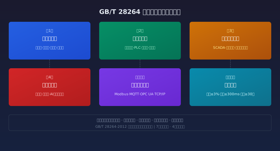
GB/T 28264 Scope and Core Framework for Crane Safety Monitoring
GB/T 28264-2012 "Safety Monitoring and Management System for Lifting Appliances" was issued by the Standardization Administration of China in 2012, marking the country's first national standard dedicated specifically to crane safety monitoring systems. The standard applies to bridge cranes, gantry cranes, tower cranes, mobile cranes, portal cranes, container cranes, construction hoists, and other types of lifting appliances. Mandatory monitoring requirements are imposed particularly on large and critical lifting equipment.
The standard defines the functional composition of the safety monitoring and management system, comprising six major modules: data acquisition unit, data processing unit, data storage unit, data output unit, control output unit, and communication interface unit. Through real-time acquisition and processing of key parameters—including lifting load, torque, travel position, wind speed, distance between cranes on the same rail, and operator commands—the system achieves comprehensive monitoring of crane operating status, automatic warning of hazardous conditions, and active protection.
From a framework perspective, the core logic of GB/T 28264 follows a closed-loop monitoring chain: "acquisition — processing — judgment — output — control." The system first collects physical quantities through various sensors, then conditions and converts the signals via A/D conversion before feeding them into the data processing unit for logical evaluation. When monitored parameters exceed preset thresholds, the system simultaneously triggers audible and visual alarms and cuts power to dangerous-direction motions through the control output unit, providing active safety protection.
7 Core Functional Modules of the Safety Monitoring System
GB/T 28264 specifies functional requirements for the safety monitoring system across seven core modules, each with defined technical indicators and performance parameters. The lifting load monitoring module requires real-time acquisition of the lifting load: a pre-warning signal is issued when the load reaches 90% of the rated lifting capacity, and the hoisting circuit power is automatically cut off at 110%. Load display accuracy must be no worse than ±3%, with a response time no greater than 0.5 seconds.
The load moment monitoring module is the core safety function for tower cranes and mobile cranes. The standard requires the load moment limiter (LML) to calculate in real time the ratio between the rated lifting capacity at the current radius and the actual load. A pre-warning is triggered when the moment reaches 90%–100% of the rated value, and hoisting and luffing motions in dangerous directions are cut off when it exceeds 100%–110%. The comprehensive accuracy of moment measurement must be no worse than ±5%, and configured parameters must be retained in the event of a power failure.
The travel limit monitoring module covers four sub-functions: hoisting height limit, load-lowering depth limit, travel limit switch, and slewing angle limit. The lifting height limit switch must cut hoisting power and apply braking at least 200 mm before the lifting spreader reaches its upper limit position. The travel limit switch must cut power to the travel direction at least 100 mm before reaching the end limit position. All travel limit switches must adopt a dual-limit design to ensure redundant safety.
The wind speed monitoring module requires an alarm when wind speed reaches the limit corresponding to the operation wind pressure, and automatic activation of the wind anchoring device when the non-operating wind pressure limit is reached. The standard specifies that the anemometer must be installed at a location representative of the actual wind conditions at the crane's highest point, with a sampling interval no greater than 2 seconds, wind speed display resolution of 0.1 m/s, and alarm accuracy within ±1 m/s.
The anti-collision monitoring module for multiple cranes on the same rail applies to two or more cranes operating on a shared runway. The system must calculate the safe distance between adjacent cranes in real time, automatically decelerate when the distance falls below the set value, and apply emergency braking when the minimum safe distance is breached. Distance measurement accuracy must be no worse than ±100 mm, with a system response time not exceeding 200 ms.
The video surveillance module must cover at least three critical viewing angles: the hoisting mechanism, the lifting spreader working area, and the long travel direction. Camera resolution must be no lower than 720P, with night vision automatically switching to infrared mode when illumination drops below 5 lux. Video footage must be retained for no less than 30 days. Video signals should overlay OSD text displaying key parameters such as lifting load, moment ratio, and wind speed, enabling synchronized recording of audio/video and operational data.
The data storage and traceability module is a key innovation distinguishing GB/T 28264 from conventional safety devices. The standard requires the system to function as a "black box," continuously storing at least 30 days of operational data—including lifting load, moment, wind speed, travel position, operator commands, and alarm events—with a sampling interval no greater than 100 ms. Stored data must be tamper-proof, exportable via USB or network, and provided in universal CSV or TXT formats.
Four-Tier System Architecture: From Sensors to Remote Supervision Platform
GB/T 28264 implicitly defines a four-tier architecture model for the safety monitoring system, a layered design philosophy closely aligned with modern Industrial Internet of Things (IoT) architectures. The first tier is the sensing and acquisition layer, comprising front-end sensing devices such as load cells, torque sensors, travel limit switches, anemometers, encoders, inclination sensors, and cameras. This layer converts physical quantities into standard electrical signals and serves as the "eyes and ears" of the entire monitoring system.
The second tier is the on-site control layer, centered on the monitoring host installed in the crane operator cab or electrical cabinet. The monitoring host performs signal conditioning, A/D conversion, logical judgment, and control output functions. It typically uses an industrial-grade embedded PC or PLC as the hardware platform, equipped with a touchscreen display of no less than 7 inches for human-machine interaction. The host must feature dual redundant power supplies and watchdog reset functionality to ensure reliable operation under harsh conditions.
The third tier is the local management station layer, deployed in the plant control room or project management office. It communicates with monitoring hosts on multiple cranes via Ethernet or industrial wireless networks. The local management station provides centralized multi-crane monitoring, data aggregation and analysis, alarm management, and automatic report generation. It is typically developed using industrial HMI/SCADA platforms, with the human-machine interface (HMI) supporting simultaneous display of operating status for multiple cranes in separate windows.
The fourth tier is the remote supervision layer, which uploads monitoring data to cloud platforms or higher-level regulatory authorities via the Internet or VPN connections. This tier enables cross-regional big-data analysis of crane safety operations, full life cycle management of equipment, fault prediction, and intelligent diagnosis. Data transmission must use SSL/TLS encryption protocols to ensure information security, and MQTT or OPC UA are recommended as the communication protocols for industrial IoT interoperability.
Typical Application Scenarios and Installation & Commissioning Essentials
For new crane manufacturing, the safety monitoring system should be installed during the assembly and commissioning phase. The lifting load sensor must be installed in series at the fixed end of the wire rope. After installation, a three-point calibration is required using standard weights or hydraulic calibration equipment—zero point at no-load, 50% of measuring range, and 100% of full scale—with calibration deviation not exceeding ±1%. The angle sensor and displacement sensor of the load moment limiter must be precisely aligned with the luffing mechanism.
For retrofit projects on existing cranes, the interface compatibility of the original electrical control system must be carefully evaluated. Kelude's retrofit solution uses an independent monitoring host communicating with the original PLC via Modbus RTU or Profibus DP protocols, enabling data acquisition without modifying the existing electrical cabinet. For older crane models without communication interfaces, a solution using add-on sensors and an independent signal acquisition module is adopted, physically isolating the monitoring system from the original control system to ensure the retrofit does not disrupt normal crane operation.
System commissioning should follow the procedure below:
Step 1: Calibrate sensor zero points and measuring ranges channel by channel. Use standard signal sources or test weights to perform linear calibration at three points—no-load, 50% of range, and 100% of full scale. Repeat each measurement 3 times and take the average, keeping deviation within ±1%.
Step 2: Verify the trigger accuracy of each alarm threshold. Test each alarm point 3 times within its positive and negative deviation range to confirm consistency, ensuring the deviation between the actual trigger value and the set value does not exceed the allowable error range.
Step 3: Test control output functions. Confirm that power to dangerous-direction motions is reliably cut off upon alarm, measure the cutoff response time to be no greater than 0.3 seconds, and verify that alarm indicator lights and the buzzer operate correctly.
Step 4: Conduct a 72-hour continuous operation burn-in test. No false alarms or missed alarms are permitted during this period. Record system operating status and key parameters every 8 hours, and generate a burn-in test report.
Field experience from Kelude across multiple large-scale projects demonstrates that a regular maintenance and calibration schedule should be established after system installation. It is recommended to perform online calibration verification of sensors quarterly, conduct a comprehensive functional test semi-annually, and commission an annual third-party inspection in accordance with GB/T 28264 to assess system performance and issue an inspection report. Critical sensors such as lifting load cells and load moment limiters typically have a service life of 5 to 8 years and should be mandatorily replaced upon expiration to ensure monitoring accuracy.
Synergistic Application of GB/T 28264 with Related Standards
GB/T 28264 does not exist in isolation within the crane standard framework; it works in conjunction with multiple national and industry standards. At the system design level, GB/T 3811-2008 Crane Design Standard specifies the crane's work duty, load combinations, and structural strength requirements—parameters that serve as the fundamental basis for setting alarm thresholds and monitoring strategies in a Safety Monitoring System. For example, a Ladle Crane operating at A7 duty classification and an installation-type Bridge Crane at A3 duty exhibit significantly different load monitoring pre-alarm thresholds and response strategies.
At the system verification level, GB/T 5905-2011 Crane Test Specification and Procedure defines the type test and factory test methods for safety devices. Under this standard, the Safety Monitoring System must undergo three major test categories: static testing, dynamic testing, and electromagnetic compatibility (EMC) testing. Static tests verify sensor accuracy and alarm threshold precision; dynamic tests validate system response characteristics under actual crane operating conditions; and EMC tests, conducted in accordance with the GB/T 17626 series, confirm system reliability in industrial electromagnetic interference environments.
At the periodic inspection level, TSG 51-2023 Crane Safety Technical Supervision Regulation has made the Safety Monitoring System a mandatory inspection item for lifting appliances. The inspection covers five areas: functional completeness of the monitoring system, sensor accuracy verification, alarm threshold validation, data storage functionality testing, and video surveillance image quality assessment. Kelude recommends that users complete a full self-inspection and preventive maintenance of the monitoring system one month prior to the annual inspection to ensure first-pass compliance.
At the electrical safety level, the electrical design of the Safety Monitoring System must also comply with GB 5226.2-2002 Safety of Machinery — Electrical Equipment of Machines — Part 32: Requirements for Hoisting Machines. The monitoring host enclosure must achieve a Protection Rating (IP) of at least IP54, outdoor-mounted sensors must be rated IP65 or higher, and all signal cables must be shielded cable with reliable grounding at both ends, maintaining a grounding resistance of no greater than 4Ω.
Monitoring Feature Configurations Across Crane Types
| Monitoring Function | Bridge Crane / Overhead Crane | Tower Crane |
|---|---|---|
| Lifting Capacity Monitoring | Mandatory Configuration | Mandatory Configuration |
| Torque Monitoring | △ Optional Configuration | Mandatory Configuration |
| Travel Limit Switch Monitoring | Mandatory Configuration | Mandatory Configuration |
| Wind Speed Monitoring | ○ Outdoor Optional | Mandatory Configuration |
| anti-collision Monitoring | Same-Track Mandatory | △ Multi-Tower Operation |
| Video Monitoring | △ Recommended Configuration | △ Recommended Configuration |
Key Performance Indicators and Inspection Standards for Safety Monitoring Systems
| Inspection Item | Standard Requirement | Inspection Method |
|---|---|---|
| Lifting Capacity Display Accuracy | ≤ ±3% | Standard Weight Three-Point Calibration |
| accuracy of moment limiter | ≤ ±5% | Luffing Multi-Point Loading Testing |
| Control Response time | ≤ 300ms | oscilloscope Measurement Cut-off Delay |
| Data Sampling Period | ≤ 100ms | Export Data Analysis Interval |
| Storage Duration | ≥ 30Consecutive Days | Timestamp Data Integrity Check |
| Electromagnetic Compatibility Grade | GB/T 17626 3Level | EMCAnechoic Chamber Radiated Immunity |
GB/T 28264 Safety Monitoring System: Key Data at a Glance
Standard Reference
GB/T 28264
Published 2012
Functional Modules
7 Modules
Full operating-condition coverage
System Architecture
4-Level Hierarchy
Sensing → Control → Management → Remote
Sampling Interval
≤100ms
Real-time data acquisition
Response Time
≤300ms
Immediate cut-off on overload
Data Storage
≥30 Days
Continuous black-box recording
Related Reading: Safety Monitoring System Selection & Application
The following technical articles cover practical aspects of selecting and applying safety monitoring systems for cranes:
• How to Select a Crane Encoder? Incremental vs. Absolute Multi-Turn — 4 Parameter Comparisons & Full Installation Guide — Encoders are the core sensors for travel monitoring; selection directly affects position detection accuracy
• How to Configure a Crane Weighing System? Sensor Selection, Installation, Calibration & Troubleshooting — Weighing systems share sensor technology with the lifting-capacity monitoring module; calibration methods are interchangeable
• How to Select Crane Limit Switches? 4 Types Compared — Parameters, Installation & Commissioning — Limit switches are the actuating elements of travel monitoring; selection must match the monitoring system's response time
• Crane Remote Control Selection: 4 Key Criteria & Pairing/Commissioning — Remote control signals are a critical input source for the monitoring system; communication compatibility must be considered
Frequently Asked Questions
Q: What are the specific data storage requirements for safety monitoring systems under GB/T 28264?
A: Clause 5.4 of GB/T 28264-2012 requires the safety monitoring system to store operational data continuously for at least 30 calendar days. Stored data must include lifting capacity, torque percentage, wind speed, travel limit switch status, operator command records, and alarm event logs. The data sampling interval must not exceed 100ms, and the storage format must incorporate tamper-proof protection. When storage capacity is nearly exhausted, the system must use a circular overwrite strategy that automatically replaces the oldest historical data; however, alarm event records must be retained for at least 90 days and must not be overwritten.
Q: What are the functional and regulatory differences between a Safety Monitoring and Management System and a conventional PLC Control System?
A: The core difference lies in purpose and compliance. A conventional PLC Control System handles crane operational logic (hoisting/lowering, crane bridge/trolley travel, etc.), whereas the Safety Monitoring and Management System is an independent safety-monitoring layer that remains fully operational even if the PLC fails — it can independently trigger alarms and cut off hazardous movements. GB/T 28264 mandates that the monitoring system use dedicated sensors and an independent processing unit, and that it must not rely solely on PLC internal register data. Lifting capacity and torque signals must be acquired directly from dedicated sensors. Additionally, the monitoring system must meet requirements for ≥30-day data storage, tamper resistance, and OSD video overlay — features that conventional PLC systems typically do not provide. Kelude's safety monitoring product line uses a dual-system independent design to ensure full compliance and safety redundancy.
Q: How do I resolve frequent false torque overload alarms on a crane safety monitoring system?
A: Frequent false alarms typically stem from three root causes. First, sensor zero drift: torque sensors may develop zero-point offset after prolonged use. Recalibrate the zero point using a standard signal source under no-load conditions; the recommended calibration interval is no more than 3 months. Second, loose sensor mounting: a loose luffing angle sensor bracket or a stuck draw-wire on the displacement sensor will produce measurement deviations. Check the torque on all mounting bolts and confirm that sensor moving parts operate freely without obstruction. Third, calibration parameters may have been inadvertently modified: verify that the boom length, load-radius curve, and other settings in the monitoring host match the crane's actual configuration. Per GB/T 28264, the system must include password-protected parameter modification and an operation log to prevent unauthorized changes. If alarms persist after addressing the above, contact the manufacturer to perform a comprehensive sensor and host inspection using professional calibration equipment.
Q: What installation parameters and retrofit requirements apply when adding a Safety Monitoring System to an older overhead crane?
A: Retrofitting an existing crane must comply with the installation requirements in Chapter 6 of GB/T 28264 Safety Monitoring and Management System. The lifting capacity sensor should be installed in series at the wire rope dead end or at the equalizer sheave, with a minimum mounting space of 150mm × 100mm reserved. The sensor measuring range must be no less than 1.5 times the rated lifting capacity. Welding of the travel limit switch mounting bracket must achieve a weld seam strength of at least 80% of the base material, and the weld seams require Magnetic Particle Inspection (MPI). The monitoring host should be located no more than 5m from the hoisting mechanism's electrical cabinet to keep signal cable lengths within limits. Power supply for the monitoring system should be tapped ahead of the crane's main disconnect switch so the system remains operational even when the main switch is off. Kelude offers an integrated retrofit package for older cranes that includes all sensors, the monitoring host, and mounting brackets, with a standard Modbus communication interface. The retrofit typically takes 2 to 3 working days, and a full crane inspection report certifying compliance with GB/T 28264 is issued upon completion.
