

Crane Bridge Rail Gauge & Span Adjustment: Tolerances & Skew
Crane Bridge Track Gauge and Span Adjustment: Tolerance Standards, Diagonal Alignment, and Wheel Skew Correction. Track gauge accuracy and span consistency of the crane wheel blocks are critical control parameters during crane installation and alignment.
Track gauge accuracy and span consistency of the crane wheel blocks are critical control parameters during crane installation and alignment. Gauge deviation and wheel skew are the primary causes of wheel rail gnawing, drive motor overload, abnormal wheel tread wear, and accelerated rail damage. Based on GB/T 10183 — Wheel Diameter Tolerances and Track Gauge Tolerances for Crane Wheel Blocks — and years of field commissioning experience, Kelude has systematically outlined the full technical requirements for crane wheel block installation and alignment.
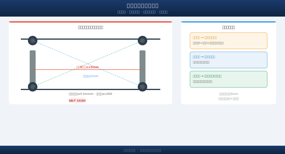
Track Gauge and Span Deviation Tolerances
GB/T 10183 specifies the permissible track gauge deviation and wheel skew tolerances for crane bridge wheel blocks. Gauge deviation is classified by span: for spans S ≤ 22.5 m, the deviation between actual and nominal gauge must not exceed ±5 mm; for spans S > 22.5 m, the deviation must not exceed ±8 mm. The diagonal difference — the difference between the two diagonal centerline distances of corresponding wheel blocks on the two rails — must not exceed 5 mm. The longitudinal offset between wheels on the same end carriage must not exceed 3 mm. Vertical wheel skew (the angle between the wheel tread surface and the rail top surface) must not exceed L/400 (where L is the wheel diameter), and horizontal wheel skew (the angle between the wheel rolling direction and the rail centerline) must not exceed 0.5 mm/m.
Measurement Methods and Instruments
Common methods for span measurement: 1) Steel tape method — a calibrated steel tape is tensioned to 50 N using a tension meter, then the center-to-center distance between the wheels at both ends is measured, with an accuracy of ±1 mm. The tape must be held parallel to the rail at a height of 100 mm above the rail top surface. 2) Laser distance measurement — a laser distance sensor is set up on the centerline of the rail top surface, with a reflective target placed at the corresponding position on the opposite rail, achieving an accuracy of ±0.5 mm. 3) Total station method — suitable for large spans (S > 30 m) or sites with significant obstructions, providing an accuracy of ±1 mm.
| Measurement Method | Measurement Accuracy | Applicability Span | Required Instruments | Advantages and Disadvantages |
|---|---|---|---|---|
| Steel Tape Method | ±1mm | S≤22.5m | Standard steel tape + tension meter | Simple Operation, Affected by Temperature and Tension |
| Laser Distance Measurement Method | ±0.5mm | S≤30m | Laser distance meterr+Reflection Target | Accuracy High, Requires Line of Sight |
| Total station method | ±1mm | S>30m | Total station + prism assembly | Suitable for Large Span, Complex Instrument Setup |
| Diagonal Measurement Method | ±1.5mm | Full Span | Steel tape + plumb line | Indirect Determination Track gauge deviation, Requires Combination with Other Methods |
Diagonal difference measurement: Mark the projected positions of the four wheel centers at both ends of the two rails (a plumb bob can be lowered from each wheel center), then measure the two diagonal lengths—the difference between them is the diagonal deviation. The crane should be in a free state during measurement (no locking, no eccentric loading), with all wheels in full contact with the rails.
Wheel skew measurement: Attach a magnetic reference block to the wheel flange, and use a laser theodolite or a frame spirit level to measure the horizontal and vertical angular deviations of the reference block. Each wheel is measured at 90°, 180°, and 270° rotation positions, and the average value is taken.
Correcting Wheel Skew and Misalignment
When wheel skew exceeds the allowable tolerance, correction is required. Kelude's on-site adjustment procedure uses the horizontal skew method: loosen the fastening bolts on the angle-type bearing housing, and insert adjustment shims between the bearing housing and the end carriage mounting face. Shim thickness t = skew amount × bearing housing spacing / wheel diameter. Shims are made of stainless steel sheet (available in 0.3mm, 0.5mm, 1mm, and 2mm thicknesses) and are placed above or below the bearing housing to deflect the wheel in the opposite direction. After adjustment, re-measurement is mandatory, with each wheel corrected iteratively until the target value is reached.
Vertical skew adjustment: If vertical skew is caused by deformation of the end carriage, the deformation must first be corrected (via flame straightening or mechanical correction) before adjusting the bearing housing base plates. If the cause is bearing housing wear or excessive bearing clearance, replace the bearing or bearing housing as applicable.
Track gauge deviation (oversize or undersize) adjustment: Gauge deviation of an individual wheel can be corrected using eccentric bearing housings or adjustment shims. However, overall gauge deviation (where all four wheels are simultaneously oversize or undersize) requires repositioning the crane rails as a whole—involving re-locating the rail clamps and rail welding (including adjusting rail joint lengths if needed). This is a major adjustment that must be performed by a professional installation contractor.
Wheel Diameter Tolerance Control
ISO 4301 specifies that crane bridge wheel diameter tolerances are classified into Grade H and Grade K. Grade H tolerance: the diameter difference between corresponding wheels on the same crane must be ≤0.2mm. Grade K tolerance: the corresponding wheel diameter difference must be ≤0.3mm. Excessive wheel diameter differences cause mismatched circumferential speeds on opposite sides, leading to skewing and wheel rail gnawing. New wheels should be matched in pairs during selection, and worn wheels should be replaced in pairs during maintenance. Wheel tread surface wear exceeding 5% of the original diameter warrants replacement.
This topic is a core component of the Complete Guide to Crane Installation, Commissioning, Acceptance & Handover series. For the next stage of installation and commissioning content, refer to Crane Electrical System On-Site Commissioning: From Basics to Advanced.
Frequently Asked Questions (FAQ)
Q: What are the primary indicators of wheel rail gnawing?
A: Typical signs of wheel rail gnawing include: sharp metallic friction sounds during bridge travel, bright spots or burrs on the wheel flanges, visible friction marks on the rail sides, and a current difference exceeding 20% between drive motors on the same side. If any of these symptoms are observed during Kelude's on-site commissioning, stop the crane immediately and inspect the track gauge and wheel skew, checking item by item against ISO 4301.
Q: At what level of tread surface wear should wheels be replaced?
A: Replacement is required when: tread surface wear exceeds 5% of the original diameter (e.g., a 500mm-diameter wheel worn by more than 25mm), flange thickness wear exceeds 50% of the original thickness, the tread surface shows spalling or cracks, or the flange is chipped. All four crane bridge wheels on the same crane should be replaced simultaneously or in matched pairs to avoid eccentric loading caused by diameter differences between new and worn wheels.
Q: What is the maximum allowable total thickness for adjustment shims?
A: The total thickness of adjustment shims between the angle-type bearing housing and the end carriage should generally not exceed 5mm (with a maximum single-shim thickness of 2mm). If more than 5mm is required, check whether the end carriage mounting surface is deformed or whether the bearing housing has been incorrectly selected—do not mask underlying deviations by adding extra shims.
Q: What follow-up checks are required after track gauge adjustment?
A: After completing track gauge adjustment, the following checks must be performed: run the bridge through its full travel three times with no abnormal noise or vibration, the current difference between drive motors on the same side must not exceed 10%, and the wheel stopping position deviation after braking must not exceed 50mm. Once the adjustment is verified as satisfactory, record the final measurement data for archival purposes.
