

Crane Main Girder Camber: Inspection & Adjustment Guide
How to Measure Crane Main Girder Camber: Inspection Methods and Adjustment Techniques. The camber of an overhead crane's main girder is a critical technical indicator of structural stiffness and load-bearing capacity. Insufficient camber increases trolley travel resistance during uphill runs, while excessive camber intensifies stress concentration at the girder-to-end-carriage connections. Precise measurement and adjustment must be performed in accordance with FEM 1.001.
Camber is the core technical parameter that defines the structural performance of a bridge crane's main girder. The designed and manufactured upward pre-arch of the girder under no-load conditions directly determines whether the elastic deflection at mid-span remains within safe limits under rated load. Insufficient camber leads to excessive deflection under load and increased trolley travel resistance; excessive camber, on the other hand, aggravates stress concentration at the girder-to-end-carriage joints. Kelude Heavy Industry provides a systematic breakdown of the full-process control points for main girder camber, covering inspection methods, adjustment techniques, and standard-based evaluation. The applicable standards are ISO 4301 for crane design and FEM 1.001 for crane test procedures.
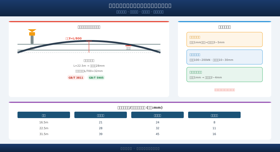
Camber Design Values and Measurement Principles
ISO 4301 specifies that the main girder of a bridge crane shall have a mid-span camber of L/1000 to L/700 (where L is the span). For Work Duty classifications A5 to A6, the camber is set at L/800; for A7 to A8, it is L/1000. For example, a crane with a 22.5 m span has a design camber of approximately 22 to 32 mm. The camber follows a parabolic or quadratic curve distribution from the girder ends toward mid-span, with the maximum value occurring at the center.
Measurement is performed using a precision level instrument or a laser level in conjunction with a steel rule. The procedure is as follows: 1) Mark measurement points at both girder ends (at the end carriage connections) and at mid-span, adding intermediate points along one side of the girder at L/4, L/2, and 3L/4 positions; 2) Set up the level instrument on the crane walkway (approximately 5 m from the main girder), take a backsight reading on the reference point, and measure the elevation differences at each marked point; 3) Calculate the vertical deviation of each measurement point relative to the line connecting the two end supports—positive values indicate camber, negative values indicate deflection. Measurements should be taken in the early morning or on overcast days to avoid thermal deformation errors caused by temperature differences between the top and bottom of the girder. After completing one side, repeat the measurement on the opposite side and take the average of the two readings.
| Spanm | Design Cambermm(L/800) | static load Deflection Limitsmm(L/700) | Permissible Residual deformationmm |
|---|---|---|---|
| 16.5 | 21 | 24 | 8 |
| 22.5 | 28 | 32 | 11 |
| 28.5 | 36 | 41 | 14 |
| 31.5 | 39 | 45 | 16 |
Evaluating Camber Changes Before and After Static Load Testing
Per FEM 1.001, static load testing is mandatory both at the factory and after installation to verify the main girder's load-bearing stiffness. The procedure involves suspending 125% of the rated load at the mid-span position, lifting it 100–200 mm off the ground, and holding it for 10 minutes while measuring mid-span deflection. After unloading, residual deformation is recorded. Acceptance criteria: 1) static load deflection ≤ L/700; 2) residual deformation after unloading ≤ 0.5‰L (i.e., L/2000). For a 22.5 m span, this corresponds to a maximum residual deformation of 11 mm. Both indicators must be met simultaneously for a pass.
Camber variation after static load testing is the most direct indicator of main girder structural integrity. Kelude performs this inspection on every unit before shipment. If camber decreases noticeably after unloading (exceeding 20% of the design value), plastic deformation has occurred in the girder's weld seams or base material, requiring a full re-inspection. If reverse camber (downward deflection at mid-span) appears after unloading, permanent structural damage has occurred, and the girder must be returned to the factory for repair or replacement.
Camber Correction Methods for Out-of-Tolerance Conditions
When camber falls outside the acceptable range (either too low or too high), the following engineering measures can be applied:
1) Spring plate adjustment: Add or remove spring plate shims at the bolted connection between the main girder and end carriage. Each 1 mm change in spring plate thickness alters camber by approximately 3–5 mm (depending on girder section stiffness and span). Suitable for fine adjustments within ±10 mm of camber deviation.
2) Prestressed tie-rod method: Weld tie-rod brackets to both sides of the main girder's bottom cover plate, install high-strength prestressed tie rods, and apply pretension. Camber is controlled by adjusting the pretension force. Suitable for moderate deviations where camber is 10–30 mm below specification. Pretension values must be calculated based on girder section parameters and span, typically ranging from 100–200 kN.
3) Connection bolt shim method: Add thin shims at the top of the end carriage connection flange while removing them from the bottom (or vice versa). The resulting angular change at the connection face alters the main girder camber. Each 1 mm of shim thickness difference adjusts camber by approximately 2–4 mm. This method is simple to execute but offers limited adjustment range.
Camber measurements must be recorded before and after any adjustment procedure. After corrections are complete, static load testing should be repeated for verification.
Key Revisions in the Updated Standard
The ISO 4301 revision introduces several changes to camber requirements: 1) a new camber design method based on actual girder stress levels replaces the previous empirical formula; 2) deflection limits are tightened for cranes in higher work duty classifications (A7~A8), changing from L/700 to L/1000; 3) guidance on applying finite element analysis to camber calculations has been added. Design and inspection personnel should stay current with these changes and apply the revised standard during installation acceptance.
This topic is a core component of the Complete Guide to Crane Installation, Commissioning, Acceptance & Handover series. For the next phase of installation and commissioning content, refer to Crane Rail Gauge and Span Adjustment: Tolerance Standards, Diagonal Alignment, and Wheel Skew Correction.
Frequently Asked Questions (FAQ)
Q: Why should camber measurements be taken at dawn or on overcast days?
A: Sunlight creates a temperature differential of 10–15°C between the top and bottom cover plates of the main girder, causing thermal bending that inflates measured camber by 5–10 mm and leads to false readings. Kelude strictly follows measurement conditions requiring temperature variation across the girder to stay within 3°C, performing measurements before sunrise or on overcast days using precision level instruments with steel rules to ensure reliable data.
Q: Has the hold duration for the 125% static load test changed?
A: FEM 1.001 specifies a 10-minute hold time for the static load test (125% of rated load). The previous standard required 15 minutes, but the revised version reduced this to 10 minutes. A trial lift at rated load should be performed before the test to confirm safety device functionality. During the hold period, girder deflection must be continuously monitored, with deflection readings recorded every 2 minutes.
Q: Does out-of-tolerance camber affect crane operational safety?
A: Slightly low camber (above 70% of the design value) has limited impact on safety but accelerates wear on the trolley travel mechanism. However, if camber falls below 50% of the design value or reverse camber develops, this constitutes a serious safety hazard requiring immediate shutdown. Excessive camber (above 150% of design value) increases trolley travel resistance at mid-span and adds bending moment at the main girder–end carriage connections, also requiring correction.
Q: Why does field camber measurement differ significantly from the factory report?
A: Discrepancies between field measurements and factory reports can result from several factors: factory measurements are taken on rigid support piers (without rail elasticity effects), while field measurements include combined elastic deformation from the crane rail and runway beam; ambient temperature differences introduce thermal deformation measurement errors; and long-distance transport may cause minor residual deformation in the main girder. Deviations within 3–5 mm are generally considered normal; anything beyond this range warrants re-measurement for confirmation.
