

Crane Structural Fatigue Life Assessment: FEA & Welding Practice
Structural Fatigue Life Assessment: Finite Element Analysis and Welding Engineering Practice. In the full life cycle management of lifting appliances, structural fatigue life assessment is the core technical approach to ensuring safe operation and preventing catastrophic fracture failures.
In the full life cycle management of lifting appliances, structural fatigue life assessment is the core technical approach to ensuring safe operation and preventing catastrophic fracture failures. As a leading crane manufacturer and engineering service provider in China, Kelude Heavy Industry has long been committed to integrating finite element analysis (FEA) with welding engineering practice, developing a comprehensive fatigue life assessment system for crane metal structures. This system covers the entire workflow — from load spectrum acquisition, stress cycle analysis, and S-N curve-based damage calculation, to Welding Procedure Specification (WPS)/Welding Procedure Qualification Record (WPQR), fatigue hotspot identification, non-destructive testing, and remaining life assessment with reinforcement design. This article draws on ISO 4301 Crane Design Standard, GB/T 19869.1-2012 Welding Procedure Qualification, GB/T 11345-2013 Non-destructive Testing of Welds — Ultrasonic Testing, and BS 7910-2019 Guidance on Methods for Assessing the Acceptability of Flaws in Metallic Structures, among other national and international standards, to systematically present Kelude Heavy Industry's technical expertise and engineering practice in structural fatigue life assessment — providing a technical reference for crane design, manufacturing, and in-service evaluation.
Fatigue Load Spectrum Development and Stress Cycle Analysis
The first step in fatigue life assessment is developing a fatigue load spectrum that accurately reflects real-world crane service conditions. Kelude Heavy Industry uses a load spectrum acquisition method based on actual duty cycles, installing strain gauges and acceleration sensors at critical load-bearing locations on the crane to capture load-time history data through long-term online monitoring. In accordance with Section 5.4 of ISO 4301, the fatigue load spectrum includes lifting load, dead weight, wind load, and inertia load components. The raw time-domain signals are first preprocessed through filtering and denoising, then converted into a series of complete stress cycles using the Rainflow Counting Algorithm, producing a bivariate distribution matrix of stress amplitude (Δσ) versus cycle count (n_i). Kelude Heavy Industry's load spectrum analysis platform automatically handles the entire chain from sensor data acquisition to S-N curve input, significantly improving the efficiency and accuracy of fatigue assessment.
S-N Curve Method and Palmgren-Miner Cumulative Damage Calculation
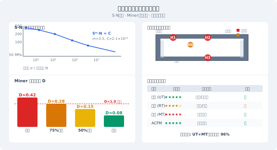
The S-N curve method (stress-life approach) is the most widely used engineering method for fatigue assessment of crane structures. In accordance with Annex K of ISO 4301, Kelude Heavy Industry selects appropriate S-N curves for different structural detail categories (e.g., butt welds, fillet welds, bolted connections). For welded structures, S-N curves are typically classified using the FAT rating system (e.g., FAT80, FAT90, FAT100), where the FAT value represents the fatigue strength (MPa) at 2×10⁶ cycles. The Palmgren-Miner Linear Cumulative Damage Rule is used to superimpose the damage effects of multi-level stress cycles: D = Σ(n_i / N_i), where n_i is the actual number of applied cycles and N_i is the allowable number of cycles at the corresponding stress amplitude (determined from the S-N curve). When the cumulative damage D reaches 1.0, the structure is considered to have reached its fatigue life limit. In engineering practice, Kelude Heavy Industry applies a safety factor by limiting the allowable cumulative damage to 0.5–0.8, accounting for load uncertainty, material scatter, and weld quality variability. For critical load-bearing components (such as the mid-span region of the main girder and end carriage connection joints), the nominal stress method and hot-spot stress method are additionally used for cross-validation to ensure the reliability of assessment results.
Welding Procedure Specification (WPS) and Qualification Record (WPQR)
Welding procedure is a critical factor affecting the fatigue life of crane structures. In accordance with GB/T 19869.1 Welding Procedure Qualification, Kelude Heavy Industry completes the full qualification process for every welded joint used in fatigue-loaded components, including: preparation of the preliminary Welding Procedure Specification (pWPS), fabrication of welding procedure qualification test specimens, mechanical testing and non-destructive testing, and issuance of the Welding Procedure Qualification Record (WPQR). Key parameters covered by welding procedure qualification include: base material grade and thickness combination, welding method (Submerged Arc Welding — SAW, Gas-Shielded Welding — GMAW, flux-cored wire arc welding — FCAW, etc.), groove type and dimensions, welding consumable type and diameter, preheat/interpass temperature range, welding heat input (kJ/mm), and post-weld heat treatment procedures. Kelude Heavy Industry's welding procedure database has accumulated more than 2,000 WPQR records, covering commonly used crane steels including Q235B (≈S235JR), Q345B (≈S355J2), Q355B (≈S355JR), and Q460D. Specifically, for fatigue hotspot regions (such as stiffener ends and corbel weld seams), low-stress welding procedures have been developed. By controlling welding heat input within the range of 1.0–1.8 kJ/mm and employing symmetrical alternating welding sequences, residual stress levels are significantly reduced, thereby improving fatigue life.
Fatigue Hotspot Identification and Non-Destructive Testing
A fatigue hotspot is a location in the structure where fatigue cracks are most likely to initiate due to geometric discontinuities, weld section changes, or stress concentration. Based on finite element analysis and engineering experience, Kelude Heavy Industry identifies typical fatigue hotspot regions in crane structures and develops targeted non-destructive testing (NDT) plans. The table below summarizes the primary fatigue hotspot locations, inspection methods, and reinforcement measures.
| Fatigue Hot Spot Location | Cause of Stress Concentration | Recommended Detection Method | Detection Standard | Reinforcement Measure |
|---|---|---|---|---|
| Main Girder Upper Flange and Web plate Connection Weld Seam | Combined Bending Normal Stress and Shear Stress | ultrasonic testing(UT)+ Magnetic Particle Testing (MT)(MT) | GB/T 11345-2013 | Grinding Weld reinforcement, Weld toe TIGRe-melting |
| Stiffener / Stiffening Rib End Weld Seam | Stress Concentration due to Sudden Section Change | Magnetic Particle Testing (MT)(MT) | GB/T 26951-2011 | Stiffener / Stiffening Rib End Radius Transition, Add Base plate |
| Bracket and Main Girder Connection Joint | Local Stress under Concentrated Load | ultrasonic testing(UT)+ Radiographic Testing (RT)(RT) | GB/T 11345-2013, GB/T 3323-2005 | Add Stiffener / Stiffening Rib, Increase Weld Seam Leg Size |
| Rail Clamp / Rail Clip Upper Flange and Main Girder Upper Flange Connection | Wheel load Contact under Cyclic Loading Fatigue | Penetrant Testing (PT)(PT) | GB/T 18851.1-2012 | Increase Clamping Plate Contact Area, Adopt Elasticity Shim Layer |
| End Carriage Bent Plate and Web plate Connection Weld Seam | Combined Bending and Torsional Stress | ultrasonic testing(UT)+ Magnetic Particle Testing (MT)(MT) | GB/T 11345-2013 | Increase Weld Seam Thickness, Optimize Bent Plate Transition Radius |
