

Electric Hoist Skewing & Wheel Rail Gnawing: 6 Causes & Fixes
📋 Quick Diagnostic Summary
Wheel rail gnawing and skewing in electric hoists is one of the most common mechanical faults in crane travel mechanisms. It manifests as abnormal friction between the wheel flange and the rail side, accompanied by metallic screeching, increased travel resistance, and higher motor current draw. Root causes fall into six categories: rail installation accuracy out of tolerance (span deviation > ±5 mm, height difference > ±2 mm), horizontal skew of the wheel block, unsynchronized drive components, frame deformation, and uneven wheel load distribution. Per GB/T 10183-2005 wheel track installation tolerance requirements and the ISO 4301 Crane Design Standard, the normal clearance between the wheel flange and rail side should be maintained at 3–5 mm. When flange wear exceeds 15% of the original thickness, the wheel block must be replaced. This article provides a complete troubleshooting workflow—from symptom identification and cause diagnosis to inspection standards and on-site adjustments—to help maintenance personnel quickly pinpoint the root cause.
4 Telltale Signs of Electric Hoist Wheel Rail Gnawing and How to Gauge Severity
Wheel rail gnawing and skewing in electric hoists rarely appears overnight—it builds up gradually. According to Kelude's after-sales maintenance data, over 80% of gnawing faults start showing noticeable symptoms after 2,000–5,000 operating hours. Field maintenance crews can use the following four symptom stages to quickly assess the severity:
① Early Stage: Intermittent Metal Scraping
The hoist emits an intermittent metallic scraping sound, occurring only at rail joints or along a specific section of the travel path. At this point, flange wear is under 5%, and light rub marks are visible on the rail side. Recommended action: clean the rail surface, check the rail joint gap (standard ≤ 2 mm), and apply rail grease.
② Mid Stage: Continuous Squealing and Increased Travel Resistance
The scraping turns into a persistent high-pitched squeal, and the travel motor current rises 15%–25% above normal. The wheel flange feels noticeably hot to the touch (> 60°C). Flange wear reaches 5%–10%, and grooves deeper than 0.5 mm appear on the rail side. Recommended action: measure the wheel-to-rail clearance using a feeler gauge and check the horizontal skew of the wheel block.
③ Severe Stage: Vibration and Rail Debris
The hoist begins to sway laterally during travel, and periodic impact vibration can be felt at the gearbox output. Metal shavings continuously shed from the rail side, with flange wear reaching 10%–15%. The motor's overload protection may trip intermittently. Recommended action: shut down immediately for inspection—measure rail span and height difference, and check the frame's diagonal dimensions.
④ Critical Stage: Wheel Climb and Derailment Risk
The wheel flange is severely worn to a knife-edge shape, with flange thickness below 50% of the original design. The rail head shows visible plastic deformation or spalling pits. The hoist may experience the dangerous condition of the flange climbing onto the top of the rail in certain sections. Recommended action: take the equipment out of service, replace the wheel block, and perform a full inspection and realignment of the rail system.
The severity levels above are based on the wheel-to-rail clearance requirements in GB/T 10183-2005 Bridge and Gantry Crane Manufacturing and Rail Installation Tolerances, combined with Kelude's years of field maintenance experience. Catching gnawing early and making timely adjustments keeps repair costs within normal maintenance budgets; delaying until the severe stage can result in both the wheel block and rail being scrapped, with replacement costs rising 5–8 times.
6 Root Causes of Electric Hoist Wheel Rail Gnawing: Diagnosis and Troubleshooting Flow
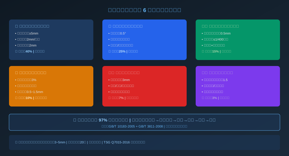
Drawing from hundreds of on-site crane repair cases, Kelude's technical team has grouped the root causes of electric hoist wheel rail gnawing into six categories. Each category has distinct fault characteristics and inspection methods. Maintenance personnel can work through the following flow from simple to complex to isolate the issue:
Category 1: Rail Installation Accuracy Out of Tolerance (~40% of Cases)
Excessive rail span deviation is the most common cause of gnawing. GB/T 10183 specifies a permissible deviation of ±3 mm for spans ≤ 10 m and ±5 mm for spans > 10 m. Measured values beyond this range result in continuous friction between the flange and rail side.
Inspection method: Use a steel tape measure or laser distance sensor to measure the span at three points—mid-span and both ends—and record the maximum deviation. Rail height difference is measured with a spirit level, with a permissible value of ≤ 2 mm at the same cross-section.
Category 2: Horizontal Skew of the Wheel Block (~25% of Cases)
The wheel axis is not perpendicular to the rail centerline, creating a horizontal skew angle. When the skew angle exceeds 0.5°, the lateral force generated during travel pushes the hoist toward one rail, causing single-side gnawing.
Inspection method: Use a theodolite or laser alignment tool to measure the angle between the wheel end face and the rail centerline. Alternatively, use the plumb-line method: take two points on the wheel end face (top and bottom) and measure the horizontal distance difference to the rail centerline.
Category 3: Vertical Tilt and Taper Error of the Wheel (~15% of Cases)
Inconsistent wheel tread taper or vertical tilt results in different rolling circle diameters. When the rolling circle diameter difference between the two sides of the driving wheel exceeds 0.5 mm, the hoist automatically veers toward the smaller diameter side during travel.
Inspection method: Use an outside micrometer to measure the wheel tread diameter at three points and take the average; use a spirit level to check vertical tilt (permissible ≤ 1/400 of the wheel diameter).
Category 4: Unsynchronized Drive Components (~10% of Cases)
The travel motors on the two sides of the hoist run at different speeds, or the brake gaps on the two sides differ, causing one-side brake drag. When the speed difference exceeds 3%, the accumulated travel speed difference creates a skewing torque.
Inspection method: Measure the motor speed on each side with a tachometer during no-load operation; measure the brake gap on each side (standard 0.5–1.5 mm) and compare for consistency.
Category 5: Frame or End Carriage Deformation (~7% of Cases)
The hoist frame deforms due to impact, overload, or uneven loading, causing the diagonal dimensions between the four wheels to change. A diagonal difference greater than 3 mm leads to noticeable gnawing.
Inspection method: Use a steel tape measure to measure the frame diagonals (cross-connecting the four wheel axle centers) and compare the difference between the two sides.
Category 6: Uneven Wheel Load Distribution (~3% of Cases)
An offset center of gravity or eccentric lifting load causes excessive wheel load differences between the two sides. When the lightly loaded side has insufficient wheel load, the wheel tends to slide laterally on the rail, resulting in gnawing.
Inspection method: Use wheel load sensors or the jacking method to measure the actual wheel load at each wheel, then calculate the wheel load unevenness coefficient. A max/min ratio greater than 1.5 is considered unacceptable.
6 Key Inspection Parameters for Electric Hoist Wheel-to-Rail Clearance and Rail Installation Accuracy
Based on the ISO 4301 Crane Design Standard, GB/T 10183-2005, and Kelude's internal quality control standards, the key inspection parameters for the electric hoist travel mechanism's wheel-and-rail system are summarized in the table below:
Electric Hoist Wheel-and-Rail System: 6 Critical Installation Accuracy Parameters
| Detection Item | Standard Allowable Value | Detection Tools and Methods |
|---|---|---|
| Crane Rail Span Deviation | Span≤10m:±3mm;>10m:±5mm | steel tape measure/Laser Distance Sensor / Laser Rangefinder, Mid-span Measurement of Rail Top |
| Crane Rail Height Difference in Same Cross-section | ≤2mm(Bridge),≤3mm(Gantry) | spirit level or total station, at every3mmeasure one point |
| Wheel flange and rail side clearance | 3~5mm(single side) | Feeler Gauge(0.05mm Accuracy), measure all four wheels |
| Wheel vertical tilt | ≤1/400Wheel Diameter(i.e.Wheel Diameter400mmwhen≤1mm) | spirit level+Square, measuring wheel End Face |
| Wheel Horizontal Skew Angle | ≤0.5°(i.e.Wheel Diameter400mmskew at the time≤3.5mm/m) | theodolite/Laser Alignment Device+Scale |
| Frame diagonal deviation | ≤3mm(Lifting Capacity≤10t) | steel coil Ruler, Cross-measure Wheelbase of Four Wheels |
Electric Hoist Wheel Rail Gnawing: 5-Step On-Site Adjustment & Acceptance Standard
The following 5-step on-site adjustment procedure is recommended in Kelude Heavy Industry's technical specification and applies to CD1/MD1 wire rope electric hoists and their matching trolleys. Before any adjustment begins, the power supply must be disconnected, verified dead, and locked out/tagged out to ensure work safety:
Step 1: Measure Baseline Data
Use a feeler gauge to measure the clearance between each wheel flange and the rail side on both sides, recording 8 gap values (one per wheel, left and right). Measure the rail span at three points (both ends and mid-span) with a steel tape. Use a spirit level to check rail height differences. Record all data on the inspection sheet and calculate the direction and magnitude of deviation.
Step 2: Correct Rail Installation Accuracy
If the rail span or height difference exceeds tolerance, correct the rail first. Loosen the rail clamp bolts and use a pry bar to fine-tune the rail's horizontal position (span correction), or add/remove shims under the rail base (height correction). Re-tighten the clamp bolts after adjustment (torque ≥ 80 N·m) and re-measure to confirm the data is within spec.
Step 3: Align the Wheel Blocks Loosen the bolts connecting the wheel block bearing housing to the frame (keep 2 diagonal bolts slightly loose). Add or remove shims (0.5mm/1mm/2mm) on the side of the bearing housing, calculate shim thickness based on measurement data. After shim adjustment, tighten bolts diagonally in sequence and re-measure wheel skew. wheel block bearing housings to the end carriage (keep two diagonal bolts slightly loose). Add or remove adjustment shims (0.5 mm / 1 mm / 2 mm) against the bearing housing side, calculating shim thickness from the measured data. Once shimming is complete, tighten the bolts in a diagonal sequence and re-check wheel alignment.
Step 4: Synchronization Tuning
Set the brake gap identically on both sides (measure with feeler gauge: 0.5–1.5 mm). Run the hoist unloaded and measure motor rotational speed on both sides with a tachometer. If the speed difference exceeds 3%, check motor wiring (star/delta connection consistency), power supply phase sequence, and rotor resistance matching.
Step 5: Load Test & Acceptance
Run the hoist unloaded for 3 round trips and listen for abnormal friction noise. Run at half load (50% of rated load) for 2 cycles and observe the wheel running path. Run once at full load, then immediately touch all four wheel flanges to check temperature (a temperature difference below 20°C passes). Re-measure the four wheel clearances — a difference of less than 2 mm between sides indicates a successful adjustment.
Electric Hoist Wheel & Rail Wear Assessment and Replacement Criteria
| Wear Location | Slight Wear(Continue Use) | Severe Wear(Must Replace) |
|---|---|---|
| Wheel Flange Thickness | Wear Mid-span Measurement of Rail Top≤Original Thickness15% | Wear Mid-span Measurement of Rail Top>Original Thickness15%, or appears Crack |
| Wheel Tread Diameter | Wear Mid-span Measurement of Rail Top≤Original Diameter2% | Wear Mid-span Measurement of Rail Top>Original Diameter2%, or spalling occurs |
| Crane Rail Head Side Wear | Wear Depth≤1mm | Wear Depth>1mmorhook with safety latch Reduction>10% |
| Rail Joint Side Clearance | ≤2mm, Height Difference in Same Cross-section≤0.5mm | Side Clearance>2mmor misaligned step occurs |
| Wheel Axle Bearing | Radial Clearance≤0.15mm, Rotation Flexible | Radial Clearance>0.15mmor there is Abnormal noise Jamming |
| Rail Clamp / Rail Clipwith Foundation | Bolt Tightening No Loosening, No Cracks in Foundation | Clamping Plate Fractureor Foundation Loosening>2mm |
Electric Hoist Wheel Flange Wear: 6 Key Data Indicators Quick-Reference Card
Standard Wheel-to-Rail Clearance
3–5mm
Per side; measure on all four wheels
Max Rail Span Deviation
±5mm
Applicable when span > 10m
Wheel Flange Wear Replacement Threshold
> 15%
Percentage of original thickness
Allowable Elevation Difference
≤ 2mm
Rail top at the same cross-section
High-Risk Operating Hours for Flange Wear
2,000–5,000h
80% of faults first appear in this window
Trolley Frame Diagonal Tolerance
≤ 3mm
For lifting capacity ≤ 10t
Kelude Heavy Industry's CD1/MD1 series electric hoist trolleys undergo 100% wheel-to-rail fit inspection before leaving the factory. The wheel blocks are machined from 42CrMo forged steel, quenched and tempered, with a tread surface hardness of HRC32–38 and a single-side flange clearance of 4mm. An adjustable bearing housing design is standard, allowing horizontal skew correction on site without removing the wheels — significantly reducing maintenance hours caused by flange rubbing. Kelude recommends a dedicated wheel-and-rail inspection every 2,000 operating hours to catch potential flange wear issues before they escalate.
📖 Related Technical Articles
The following hand-picked articles from the Kelude Heavy Industry technical blog cover crane travel mechanism maintenance topics for operations and maintenance personnel:
Frequently Asked Questions
Q: How do I tell the difference between normal wheel-to-rail contact and flange rubbing (wheel rail gnawing) on an electric hoist?
A: Normal wheel-to-rail contact involves only rolling friction between the wheel tread and the rail head — the wheel flange should never touch the rail side. Flange rubbing, by contrast, is unwanted sliding friction between the flange and the rail side. Here's how to check: use a feeler gauge to measure the gap between the flange and the rail side. If you have 3–5mm of clearance on both sides, contact is normal. If the clearance on one side is zero, accompanied by a metallic scraping sound, a shiny or hot flange, flange rubbing has occurred. Kelude recommends measuring this clearance monthly and logging the trend.
Q: What does the GB/T 10183 standard specify for rail elevation differences on crane tracks?
A: GB/T 10183-2005 specifies that for bridge cranes, the elevation difference between the tops of two rails at the same cross-section must be ≤ 2mm (when the track gauge is ≤ 10m); for gantry cranes, the limit is ≤ 3mm. Along the rail length, the elevation difference within any 2m segment must be ≤ 1mm. If this tolerance is exceeded, the hoist generates a lateral force that pushes the wheels toward the lower rail — a primary cause of single-side flange rubbing. For inspection, use a spirit level with NA2 accuracy or better, measuring at 3m intervals along the track. Kelude's rail installation team uses laser leveling equipment to keep the full-length elevation difference within 1mm.
Q: At what wear level must an electric hoist wheel be replaced due to flange rubbing?
A: According to ISO 4301 Crane Design Standard and TSG Q7015-2016 (Periodic Inspection Rules for Lifting Appliances), a wheel must be replaced immediately if any of the following conditions are met: ① flange thickness wear reaches 50% of the original thickness (i.e., remaining thickness < 50% of original); ② tread wear reaches 2% of the original wheel diameter; ③ cracks or spalling appear on the tread or flange; ④ pits deeper than 1mm are found on the tread surface. In practice, Kelude recommends scheduling a replacement once flange wear exceeds 15% of original thickness to prevent accelerated wear from causing collateral damage to the crane rail.
Q: How much does it typically cost to correct electric hoist tracking/skewing?
A: For rail and wheel alignment adjustments only (no parts replaced), Kelude Heavy Industry charges $220–$440 per service visit, which includes the use of measuring instruments and two technicians for half a day. The final quote depends on the crane rail length and the complexity of the adjustment. If wheel block replacement is required, a single wheel block for the CD1 model costs approximately $30–$75 depending on capacity, while the MD1 two-speed wheel block runs about 30% higher. Replacing all four wheel blocks, including labor, typically costs $300–$590. In cases where severe rail deformation calls for a full section replacement, the rail material alone runs about $12–$22 per meter. To avoid repair bills exceeding $740 from unexpected failures, we recommend a preventive inspection and adjustment every 2,000 operating hours at a cost of $75–$120.
