

Crane Current Collector Installation: 6 Gap Adjustments & Power Test
📋 Key Takeaways
The current collector is a critical component of the crane power supply system, and installation quality directly impacts operational safety. This article details the six key clearance parameters for current collector installation: brush contact pressure of 15–25 N, vertical deviation ≤ ±3 mm, conductor rail joint gap ≤ 0.5 mm, insulation resistance ≥ 1 MΩ (measured with a 500 V megohmmeter), carbon brush wear allowance ≥ 5 mm, and levelness ≤ 1/1000. A three-step power-on commissioning procedure—insulation testing → no-load test run → loaded temperature rise check—ensures first-pass installation and prevents common faults such as arcing, sparking, and power-off shutdowns.
The installation and commissioning of crane current collectors must comply with multiple national and industry standards. ISO 4301 (Crane Design Standard) defines the design principles and safety factor requirements for crane power supply systems, serving as the basis for current collector selection. DIN 15063 (Electrical Equipment for Cranes) specifies detailed technical requirements for the electrical performance, insulation class, and protection of conductor rails and current collectors. All Kelude cranes are installed and commissioned in strict compliance with these standards.
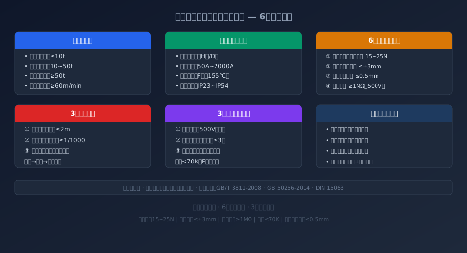
Current Collector Types and Structural Principles
A current collector is the power transfer device that connects the fixed conductor rail to the moving electrical equipment on a crane. It consists of four main components: carbon brushes (or copper-graphite brush plates), brush holders, a spring-loaded pressure mechanism, and an insulated mounting bracket. The carbon brushes maintain sliding contact with the conductor rail surface, and the spring mechanism ensures a constant contact pressure, transmitting electrical power from the rail to the crane's travel motors, hoisting motors, and control system.
Depending on crane capacity and travel speed, current collectors fall into four types:
① Single-arm current collector: Suitable for light-duty cranes up to 10 t. Simple structure and low cost, but limited resistance to sway.
② Double-arm current collector: Designed for medium-duty applications from 10 to 50 t. Dual brushes in parallel improve power supply reliability by 50%.
③ Multi-pole current collector: Fits heavy-duty cranes above 50 t, supporting multiple independent power circuits.
④ Twin-brush current collector: Engineered for high-speed operation (≥ 60 m/min), with a built-in damping mechanism to maintain stable contact at speed.
Kelude Heavy Industry standardizes on double-arm current collectors with copper-graphite brush plates, offering conductivity ≥ 85% IACS and a service life of up to 100,000 sliding cycles.
Pre-Installation Preparation and Base Parameter Standards
Three preparation steps are required before installation. First, verify that the conductor rail model matches the current collector specification, confirming that the rated current, number of poles, and insulation class meet the crane's total power demand. The conductor rail's rated current should be ≥ total crane power ÷ (√3 × 380 V), with a 20% safety margin.
Second, inspect the conductor rail housing and copper conductor bars for oxidation or mechanical damage, and check the insulating housing for cracks. Measure phase-to-phase and phase-to-ground insulation resistance using a 500 V megohmmeter. While GB 50256-2014 requires ≥ 1 MΩ, Kelude's internal standard mandates ≥ 5 MΩ to ensure long-term reliability.
Third, position the mounting brackets so that the overall levelness of the conductor rail is ≤ 1/1000, with bracket spacing not exceeding 2 m.
For bridge cranes, the conductor rail is typically installed at a height of 3–4 m above the crane runway rail to prevent mechanical interference over the full travel range. Kelude Heavy Industry offers a pre-installation Technical Briefing service, dispatching engineers for on-site positioning and layout guidance.
Six Key Clearance Parameters for Installation and Commissioning
The core of current collector installation lies in precisely controlling six clearance parameters. The following steps should be performed in sequence:
① Brush contact pressure adjustment: Use a spring scale to measure the normal force of the brush plate against the conductor rail. The standard value is 15–25 N. Pressure below 10 N causes arcing and brush plate erosion; pressure above 30 N accelerates carbon brush wear and increases running resistance. Adjust by rotating the nut at the rear of the brush holder—clockwise to increase pressure, counterclockwise to decrease—then lock and re-measure.
② Vertical deviation calibration: Measure the vertical deviation of the collector centerline relative to the conductor rail centerline at the start, midpoint, and end of the crane bridge travel. The requirement is ≤ ±3 mm. Kelude uses laser alignment equipment for calibration; if deviation exceeds 3 mm, adjust by adding or removing shims on the collector mounting base.
③ Conductor rail joint gap control: The gap between adjacent conductor rail segments at joints must be ≤ 0.5 mm, with joint offset ≤ 0.3 mm. Excessive gaps cause impact vibration and arcing as the carbon brush passes. Fill the joint with conductive grease and tighten the connecting bolts to the specified torque (15–20 N·m for M8 bolts).
④ Insulation resistance testing: After installation, use a 500 V megohmmeter to measure phase-to-ground and phase-to-phase insulation resistance. The standard requires ≥ 1 MΩ. ISO 4301 permits insulation resistance to drop to 0.5 MΩ in humid environments, but Kelude enforces an internal standard of ≥ 2 MΩ. Disconnect all loads and verify the surge protector has not been triggered before testing.
⑤ Carbon brush wear allowance check: The free length of the carbon brush must be at least 2/3 of the design length, meaning a wear allowance of ≥ 5 mm. When the remaining brush length falls below 5 mm, the spring pressure can no longer maintain 15 N and the brush must be replaced immediately. Inspect brush wear every 500 operating hours.
⑥ Levelness inspection: The levelness deviation of the brush holder relative to the conductor rail must be ≤ 1/1000, i.e., ≤ 1 mm per meter of length. Use a spirit level or laser level to check across the full length. If out of tolerance, adjust the tightness of the collector mounting plate bolts until levelness is achieved.
Three-Step Power-On Commissioning Procedure
Once all clearance parameters pass inspection, proceed with power-on commissioning in the following three steps:
Step 1—Insulation verification: Re-check insulation resistance for each phase using a 500 V megohmmeter, confirming ≥ 1 MΩ. Verify that the grounding wire (PE) is securely connected and that grounding resistance is ≤ 4 Ω. Use a multimeter to confirm three-phase voltage is within 380 V ± 10% and that phase sequence is correct. Kelude's commissioning procedure requires insulation test data to be recorded and filed as part of the acceptance documentation.
Step 2—No-load full-travel test: With the crane unloaded, run the crane bridge at low speed (≤ 20 m/min) for at least three full round trips. Observe that the carbon brushes maintain smooth contact with the conductor rail—no abnormal noise and no visible sparking. DIN 15063 specifies that spark class during no-load operation must be ≤ 1¼ (virtually no visible sparks). Then run at rated speed and check for brush bounce or disengagement.
Step 3—Loaded test and temperature rise check: Load the crane to its rated load and run the bridge for 30 minutes of continuous round trips. Use an infrared thermometer to measure the temperature rise at the carbon brush contact area. ISO 4301 specifies a maximum temperature rise of ≤ 70 K for Class F insulation (maximum allowable 110 °C at 40 °C ambient temperature). Simultaneously measure phase current balance; the unbalance among the three phases must be ≤ 10%. Only after all indicators pass may the Acceptance Report be signed. Kelude provides complete commissioning records as part of the equipment documentation.
Common Installation Issues and Troubleshooting
Arcing and sparking are the most common consequences of poor installation, typically caused by insufficient brush contact pressure or oxidation on the conductor rail surface. The remedy is to first clean the conductor rail surface with anhydrous alcohol, then re-measure and adjust the contact pressure to approximately 20 N (the midpoint of the standard range), and finally run a no-load test to confirm the sparking is eliminated. If sparking persists after adjustment, check for stepped misalignment at the rail joints.
Abnormal carbon brush wear is usually caused by one of two factors:
First, excessive contact pressure (above 30 N), where friction energy converts to heat and accelerates wear.
Second, out-of-tolerance conductor rail levelness, causing lateral forces that lead to uneven brush wear.
The corrective actions are to adjust the pressure back to the standard range, re-calibrate the rail levelness to ≤ 1/1000, and replace any brushes that have already worn unevenly. Kelude recommends a dedicated current collector inspection once per quarter.
Power-off shutdowns typically result from carbon brushes worn to their limit, causing contact interruption, or from spring failure in the collector mechanism. As an emergency measure, temporary shims can compensate for lost spring pressure, but the permanent solution is to replace the brush assembly. Kelude's after-sales team provides 24-hour emergency spare parts delivery, with common brush models arriving on-site within 48 hours.
Current Collector Parameter Comparison Table
Kelude Heavy Industry: Overhead Crane & Gantry Crane Manufacturer
Kelude Heavy Industry is a professional manufacturer of industrial overhead cranes and gantry cranes, offering a full range of material handling solutions for workshops, warehouses, and production lines. With a strong focus on safety, performance, and long-term reliability, our cranes are engineered to meet the demands of heavy-duty industrial environments across the United States and Europe.
Frequently Asked Questions
Q: What is the typical lead time for a standard overhead crane?
A: Lead time depends on the crane configuration and current production schedule. For standard single-girder cranes, typical delivery is 4 to 6 weeks. Custom-engineered double-girder or explosion-proof cranes may require 8 to 12 weeks.
Q: Do you provide installation and commissioning services?
A: Yes, we offer supervised installation and commissioning services. Our technical team can also provide operator training and after-sales support to ensure safe and efficient crane operation.
Q: Can you supply cranes with special voltage or control requirements?
A: Absolutely. We can customize electrical systems to match local power supply standards, including 230V, 460V, and 575V configurations, as well as variable-frequency drives (VFD) for precise speed control.
Q: What is the warranty period for Kelude cranes?
A: We provide a standard 12-month warranty covering manufacturing defects. Extended warranty options are available upon request.
Installation Acceptance & Inspection Standards Reference Table
| Inspection Item | Standard Requirement | Inspection Method |
|---|---|---|
| Insulation Resistance | ≥1MΩ(GB 50256) | 500VMegohmmeter (Insulation Tester) |
| Contact pressure | 15~25N(DIN 15063) | Spring Dynamometer |
| Vertical Deviation | ≤±3mm | Laser Alignment Instrument |
| Joint Clearance | ≤0.5mm | Feeler gauge |
| temperature rise limit | ≤70K(FClass insulation) | Infrared thermometer |
| Grounding Resistance | ≤4Ω | ground resistance tester |
Section 8: Key Installation Data for Conductor Rail Current Collectors
A: Contact Pressure
15~25N
Per DIN 15063
Insulation Resistance
≥1MΩ
Tested with 500V megohmmeter
Vertical Deviation
≤±3mm
Laser alignment check
Joint Gap
≤0.5mm
Measured with feeler gauge
Temperature Rise Limit
≤70K
Class F insulation (155°C)
Carbon Brush Wear Limit
≥5mm
Replace below this value
📖 Related Reading
🔹 ISO 4301 Crane Design Standard: Selection method for 9 load combinations and work duty classifications from A1 to A8
🔹 DIN 15063 — Interpretation of the Standard for Electrical Control Equipment in Cranes
🔹 GB/T 10183 Crane Rail Mounting Tolerances: 5 Key Indicators and a 3-Step Inspection & Acceptance Method
🔹 Wire Rope Clip Installation Direction and Quantity Standards: GB/T 5976 Clamp Reference Table and a 5-Step Compliance Check
Frequently Asked Questions
Q: How do I fix arcing or sparking on a conductor rail current collector?
A: Arcing is typically caused by insufficient contact pressure on the carbon brush or oxidation on the conductor rail surface. Corrective steps: ① Clean the conductor rail surface with anhydrous alcohol; ② Check contact pressure with a spring scale and adjust the brush holder nut to 20N (mid-range of the 15–25N DIN 15063 specification); ③ Verify that joint gaps do not exceed 0.5mm and fill any oversized gaps with conductive paste; ④ Run a no-load test to confirm the arcing is eliminated. Kelude recommends cleaning the conductor rail surface monthly to prevent arcing issues.
Q: What does ISO 4301 specify for insulation resistance on crane current collectors?
A: ISO 4301 requires insulation resistance of the crane electrical system to be ≥1MΩ under normal conditions (measured with a 500V megohmmeter), with a permissible drop to 0.5MΩ in humid environments. GB 50256-2014 further mandates ≥1MΩ after installation is complete. Kelude applies a stricter internal standard of ≥2MΩ, measuring phase-to-ground and phase-to-phase insulation resistance on every conductor during the Factory Acceptance Test, with results recorded in the Product Certificate. Note: Disconnect all VFDs, PLCs, and other electronic devices before testing to prevent high-voltage damage to components.
Q: At what wear length should the carbon brush on a current collector be replaced?
A: The replacement threshold is when the remaining carbon brush length falls below 5mm, or less than two-thirds of the original free length. Once worn to this limit, spring pressure can no longer maintain the required 15N contact force, leading to poor contact and arcing. DIN 15063 specifies a carbon brush service life of ≥50,000 sliding cycles for single-arm designs and ≥100,000 cycles for double-arm designs. We recommend inspecting brush wear every 500 operating hours and tracking the wear rate to predict the Replacement Interval. Kelude supplies OEM carbon brush spare parts with conductivity ≥85% IACS, compatible with all standard conductor rail systems.
Q: What size conductor rail current collector do I need for a 3t electric hoist?
A: For a 3t electric hoist, the current collector rating depends on the hoist's motor power and duty cycle rather than the lifting capacity alone. As a general guideline, a 3t hoist with a typical 4.5kW motor and variable-frequency drive (VFD) control requires a current collector rated at 80A or higher. The conductor rail cross-section should be selected based on the total connected load and the crane's work duty classification. For a precise recommendation, consult the crane manufacturer's specifications or contact Kelude with your hoist model and motor power details.
A: The total power of a 3t electric hoist typically ranges from 4.5 to 7.5 kW (hoisting motor 4.5 kW + travel motor 0.4 kW × 2), with a rated current of approximately 10–15 A at 380 V. An H-type enclosed conductor rail rated at 50 A is recommended, providing more than 3× headroom, and a single-arm current collector is sufficient for this application. Set the contact pressure of the current collector to 15 N, and use copper-graphite alloy carbon brushes sized 20 × 25 × 40 mm. For demanding environments such as foundries or dusty, high-temperature casting shops, we recommend upgrading to a double-arm current collector and selecting a heavy-duty conductor rail with an IP54 protection rating. Kelude Heavy Industry offers free sizing and selection assistance — call our technical hotline for a customized solution.
