

Crane Coupling Elastomer Aging: 6 Detection & Replacement Guide
Aging of crane coupling elastomers (spider inserts, pin bushings, serpentine springs, diaphragms) leads to reduced transmission accuracy, increased vibration, and even shaft fracture. Six inspection methods—visual inspection, clearance measurement, hardness testing, torque decay analysis, vibration spectrum analysis, and disassembly inspection—can detect aging at an early stage. Replacement intervals should be determined per ISO 4301 and industry best practices.
Couplings are critical transmission components connecting the crane electric motor to the gearbox (or the gearbox to the drum), performing three key functions: transmitting torque, compensating for shaft alignment deviations, and cushioning impact loads. As the wear-prone element within the coupling, the elastomer's condition directly affects the safety and reliability of the entire crane. Over extended service, elastomeric materials undergo fatigue creep, chemical aging, and thermo-oxidative degradation, resulting in reduced stiffness, lower damping capacity, and diminished load-carrying capability. This article systematically outlines the full life cycle management of coupling elastomers across three dimensions: detection methods, acceptance criteria, and replacement intervals.
Role of Coupling Elastomers and Aging Mechanisms
Coupling elastomers serve three primary functions: transmitting torque while absorbing transient overloads, compensating for shaft alignment deviations between the motor shaft and the gearbox input shaft (covering axial, radial, and angular misalignment), and cushioning impact loads during start-up and braking. The four main elastomer material families are polyurethane (PU), nitrile rubber (NBR), natural rubber (NR), and metallic springs (serpentine springs and diaphragm packs). Each material exhibits distinct failure modes: polyurethane softens and deforms at elevated temperatures (above 80°C), nitrile rubber swells in oil-contaminated environments, natural rubber develops surface cracking from ozone and UV exposure, and metallic elastomers primarily fail through fatigue fracture.
Aging typically progresses through three stages: initial micro-crack formation (no visible external signs, but molecular chain scission has begun), intermediate macro-crack propagation (visible surface cracks or discoloration, with increasing clearances), and final stage of sharply reduced load capacity (abnormal vibration and noise during operation). Research indicates that when an elastomer reaches approximately 70% of its service life, its dynamic stiffness drops by about 15%–25% and damping coefficient decreases by roughly 30%–40%. At this point, the elastomer may still appear acceptable cosmetically, yet vibration levels in the drive train have already risen noticeably.
Six Methods for Detecting Elastomer Aging
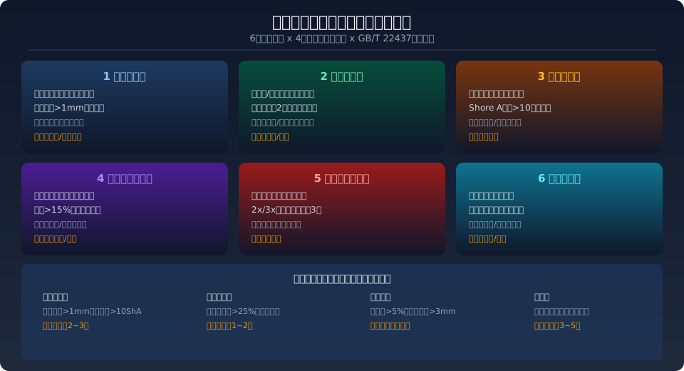
① Visual Inspection — The simplest routine check. Examine the elastomer surface for radial or circumferential cracks, color changes from the original shade to dark brown or gray-white (indicative of thermo-oxidative aging), and any material extrusion or flaking debris. For jaw couplings, check crack depth at the root of the jaws; for pin-type bushings, look for circumferential cracking and compression deformation; for serpentine springs, inspect for broken coils and surface corrosion; for diaphragm packs, check for fatigue cracks and bending deformation. Acceptance rule: replace if any through-crack is found, if discoloration depth exceeds 1 mm, or if material extrusion exceeds 15% of the original dimension.
② Clearance Measurement — Use feeler gauges or a dial micrometer to measure axial and radial clearance between the two coupling halves, comparing against the original installation values. Normal axial clearance typically ranges from 2 to 5 mm (depending on model and size), with radial runout below 0.05–0.10 mm. When axial clearance increases to more than twice the original value, or radial runout exceeds 0.20 mm, severe wear or permanent deformation of the elastomer is indicated. This method is most effective for gear couplings and serpentine spring couplings, where elastomer wear directly translates into clearance changes. Quarterly measurements with trend tracking are recommended.
③ Hardness Testing — Use a Shore durometer (Type A or Type D, depending on the elastomer's hardness range) and take 3–5 readings across the elastomer surface, averaging the results. New parts typically measure Shore A 70–95 (polyurethane runs harder; nitrile rubber softer). When the measured hardness drops by more than 10 Shore A units from the new-part value, significant chemical aging or thermal degradation has occurred, and the elastic modulus has irreversibly declined. Take readings on the primary load-bearing surfaces (jaw faces or cylindrical surfaces), avoiding any cracked areas.
④ Torque Decay Testing — During scheduled downtime, use a torque wrench or strain gauges to measure the torque transmitted by the coupling at a specific angular deflection, comparing against the rated torque. A healthy elastomer should transmit 100% of nameplate torque at the rated deflection (typically 2–5°). When measured transmitted torque falls below 85% of the rated value, the elastomer's stiffness has degraded significantly. This method is particularly effective for jaw couplings and diaphragm couplings. For critical applications (such as hoisting mechanisms on metallurgical cranes), semi-annual testing with torque decay curve logging is recommended.
⑤ Vibration Spectrum Analysis — Install a dynamic acceleration sensor near the coupling to capture vibration spectrum data. A healthy coupling exhibits a dominant vibration peak at 1× running frequency (motor rotational speed) with low amplitude. As the elastomer ages, stiffness asymmetry and increased clearance cause the 2× and 3× running frequency peaks to rise markedly. Empirical criteria: schedule elastomer replacement when the 2× vibration amplitude exceeds three times the baseline, or when the 3× amplitude exceeds twice the baseline. Cross-referencing with ISO 10816-3 equipment classification, vibration severity reaching Zone C (4.5–11.2 mm/s) or above warrants close attention to coupling condition.
⑥ Disassembly Inspection — During annual overhaul or equipment relocation, fully disassemble the coupling and conduct a comprehensive elastomer examination. This includes: measuring the fit clearance between the bore and shaft (standard H7/g6 fit; repair required if clearance exceeds 0.10 mm), checking keyway wear (repair required if key width wear exceeds 0.10 mm from the original value), and testing geometric recovery rate (the elastomer should recover to at least 95% of its original dimensions within 30 minutes after compression). Disassembly inspection criteria: replace the elastomer if any of the three checks fails and cannot be repaired.
Aging Characteristics by Coupling Type
Jaw Coupling (elastomer: polyurethane PU or nitrile rubber NBR) — The most common coupling type on cranes, featuring a star-shaped spider insert. Aging progression: micro-cracks at the jaw root, deepening into severe crazing, jaw tooth fracture and detachment, and a sharp drop in transmitted torque. Polyurethane elastomers soften approximately 3–5 times faster in high-temperature environments (continuous operation above 80°C). Kelude aftermarket data shows that jaw coupling spiders on metallurgical workshop cranes have an average replacement interval roughly 40% shorter than those in ambient-temperature workshops.
Pin-and-Bushing Coupling (elastomer: bushing + pin assembly) — Typical aging signs include circumferential cracking and compression deformation of the bushing. Replace the entire set when the bushing is compressed beyond 25% of its original thickness (e.g., from 10 mm down to 7.5 mm), or when more than three radial cracks appear within one week. Inspect the pin's taper fit (typically 1:10 taper between pin and bore); replace the pin along with the bushings if loosening or eccentric wear is found.
Serpentine Spring Coupling (elastomer: alloy spring steel serpentine spring) — Primary aging modes are metal fatigue and corrosion. Inspect spring surfaces for corrosion pitting (replace if pit depth exceeds 0.2 mm), check for uneven pitch spacing (replace if the gap between adjacent coils differs by more than 0.3 mm), and verify spring engagement depth in the tooth grooves (replace if wear reduces engagement depth by more than one-third). Replace the entire spring set if more than 5% of the total coils are broken.
Diaphragm Coupling (elastomer: stainless steel diaphragm pack) — Used in high-speed, high-precision drive applications. Aging detection relies primarily on visual inspection for fatigue cracks on the diaphragm surface (especially around bolt holes and in the fillet transition zones), bending deformation (measured with a surface plate and feeler gauge; replace if flatness deviation exceeds 0.05 mm/100 mm), and tightening torque of the diaphragm pack bolts (check each bolt and re-torque to the calibrated specification). While the theoretical service life of a diaphragm pack is relatively long (3–5 years), actual life varies widely under harsh operating conditions, so replacement decisions should not be based on runtime alone.
Elastomer Replacement Interval Reference
| Coupling Type | Elasticity Material | Daily Inspection Period | Details Detection Period | Recommended Replacement Interval | Criteria Standard |
|---|---|---|---|---|---|
| Jaw Coupling / Spider Coupling | PUPolyurethane | Visual per shift | Quarterly measurement Hardness | 2~3Year/8000h | Crack Depth>1mmor Hardness Drop>10ShA |
| Jaw Coupling / Spider Coupling | NBRNitrile rubber | Visual per shift | Quarterly measurement Hardness | 1.5~2Year/5000h | Swelling rate>3%or Hardness Drop>10ShA |
| Pin Coupling | NBRElasticity Ring | Visual weekly | Monthly clearance measurement | 1~2Year/4000h | Compression set>25%or circumferential cracking |
| Serpentine Spring Coupling | Alloy Spring Steel | Visual weekly | Quarterly clearance measurement | 3~5Year/10000h | Spring fracture>5%or axial play>3mm |
| diaphragm coupling | Stainless Steel Diaphragm | Visual monthly | Semi-annual vibration analysis | 3~5Year/12000h | Fatigue Crackor bending Deformation |
| crowned gear coupling | Tooth surface Grease | Weekly greasing | Monthly tooth thickness measurement | According to Wear Quantitative assessment | Monthly tooth thickness measurement Wear>15% |
Note: The replacement intervals above are reference values for normal workshop conditions (0–40°C) and work duty A3 to A5. In high-temperature environments (above 60°C), heavy dust, strong corrosion, or work duty A6 to A8, the replacement interval should be shortened by 30%–50%. Refer to the relevant provisions in GB/T 22437 series standards for crane couplings and FEM 9.861 — Design Specification for Crane Couplings.
Elastic Element Replacement: Key Steps and Precautions
Before you begin — Verify that the replacement elastic element matches the original part number and specification (check the coupling nameplate for the model and the hardness code of the elastic element). Inspect the new part for surface defects such as cracks, porosity, or embedded impurities. Prepare the required tools: a bearing puller (to remove the coupling hub), feeler gauges (to check clearance), a torque wrench (to tighten to the calibrated value), and a dial indicator (for shaft alignment).
Replacement procedure — When removing the old elastic element, take care not to score the mounting faces or keyways of the coupling hubs. Before installing the new element, clean the hub pockets thoroughly (remove old grease and wear debris) and apply a uniform coat of molybdenum disulfide grease (for jaw couplings) or extreme-pressure lithium grease (for serpentine spring couplings). After installation, re-check shaft alignment: maximum axial deviation 0.05 mm, maximum radial deviation 0.03 mm (per GB/T 22437.1 accuracy grade requirements).
Post-replacement trial run — Run the crane unloaded for 5 minutes and check the coupling for abnormal heat (hand-feel temperature should not exceed 15°C above ambient), unusual noise, or vibration. Then run at 50% rated load for 10 minutes and re-check the same indicators. Only after confirming normal operation should the crane return to full-load service. For the first week after replacement, inspect the elastic element daily and re-torque the coupling bolts.
Related Reading and Standards
Further reading: Interpretation of GB/T 22437 — Crane Couplings Standard | Interpretation of FEM 9.861 — Design Specification for Crane Couplings | Interpretation of GB/T 23203-2008 — Couplings for General Purpose Bridge Cranes
Frequently Asked Questions
Q: What specific requirements does GB/T 22437 place on the material and inspection of coupling elastic elements?
A: The GB/T 22437 series specifies material properties, mechanical performance, and inspection methods for elastic elements by coupling type. Tensile strength, tear strength, and compression set are mandatory test items, with batch sampling required for each lot. The standard also defines storage conditions (avoid direct sunlight and oil contamination; storage temperature −10°C to 40°C) and shelf life (3 years from date of manufacture for polyurethane elastomers, 2 years for nitrile rubber). All elastic elements supplied with Kelude cranes come with material test certificates.
Q: How much shorter is the service life of polyurethane jaw coupling spiders in high-temperature workshops?
A: Polyurethane elastomer life is highly temperature-sensitive. At normal ambient temperature (25°C), the design life is approximately 8,000 hours, but the aging rate roughly increases by a factor of 1.8–2.2 for every 10°C rise in temperature. In steel mill workshops where continuous operating temperatures exceed 60°C, the actual service life of a jaw coupling spider typically drops to 3,000–4,000 hours (about 1–1.5 years). For high-temperature environments, we recommend switching to FKM (fluoroelastomer) spiders or replacing the jaw coupling with a serpentine spring coupling, which can withstand temperatures up to 120–150°C.
Q: What cascading failures can a damaged coupling elastic element cause, and how can they be caught early through routine inspection?
A: Once the elastic element fails completely, the metal coupling hubs come into direct contact, which can quickly damage the motor shaft, gearbox input shaft bearings, and gears. The typical failure chain is: spiderFracture → hub tooth face scoring → increased radial load on the gearbox input shaft → bearing raceway fatigue spalling → poor gear meshing → complete gearbox failure. Early warning signs to watch for during routine inspection include: intermittent metallic knocking sounds from the coupling area during operation, periodic fluctuations in motor current (swings exceeding 15% of normal), and rubber debris or metal powder accumulating inside the coupling guard.
Q: What support does Kelude Heavy Industry offer for coupling elastic element supply and technical service?
A: Kelude Heavy Industry maintains a coupling elastic element record for every crane we ship, and develops a customized replacement schedule based on the equipment's work duty and operating environment. We stock elastic elements for all common coupling models — covering jaw, pin, serpentine spring, and diaphragm types — with 48-hour dispatch available. Our technical service team provides value-added support including online vibration monitoring data analysis, on-site dynamic balancing, and elastic element life prediction. Consultation hotline: 400-086-9590.
