

Crane Overload Limiter vs Load Moment Limiter: Working Principles
? An overload limiter measures a single load weight and is used on fixed-gauge cranes such as overhead, gantry, and hoist types, with thresholds set at 110% for pre-warning and 125% for forced cutoff (per ISO 4306, General Purpose Bridge Crane). A load moment limiter (LML) measures the real-time product of load × radius and is dedicated to luffing-type cranes such as jib, tower, and mobile units, dynamically tripping based on the load moment curve (per ISO 10245-5:2005).
Among crane safety protection devices, overload limiters and load moment limiters are the two most commonly confused pieces of equipment. Although both fall under the category of overload protection, they differ fundamentally in operating principle, applicable crane types, installation location, and calibration standards. This article provides a detailed technical comparison of the two limiter types from an engineering perspective to support accurate selection and day-to-day maintenance.
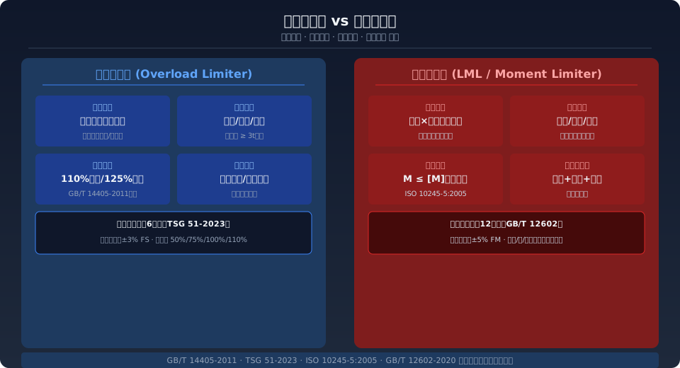
Overload Limiter vs. Load Moment Limiter: Key Differences
An overload limiter is a safety device that measures the actual weight of the lifting load, compares it against a preset rated value, and automatically cuts hoisting power or triggers an alarm. Its operating principle involves a tension sensor (or pin-type sensor) mounted at the fixed pulley shaft end or on the hook beam, which converts the load force into a 4–20 mA analog electrical signal. The controller then compares this signal against the set threshold: at 110% of rated capacity, it issues an audible and visual pre-warning and cuts the hoisting-up circuit (while keeping the lowering circuit operational); at 125%, it forcibly de-energizes the hoisting contactor coil for a hard stop. The core logic of an overload limiter is single-variable comparison—it only checks whether the absolute mass of the current load exceeds the rated lifting capacity.
A load moment limiter (LML) is a safety protection device designed specifically for luffing-type cranes. Unlike an overload limiter, the LML simultaneously acquires two variables—the lifting load and the boom radius—and calculates the real-time load moment (load × radius), then compares it against the rated load moment curve for that specific working radius. When the actual moment reaches 90%–100% of the rated value, a pre-warning is issued; above 100%, it automatically stops dangerous directional movements (prohibiting radius increase and hoisting up, while permitting radius decrease and lowering). Its core logic is dynamic load moment curve comparison: the same load at different radii can yield entirely different safety verdicts.
Crane Types and Applicable Standards
Overload limiters are suited to crane types where the lifting height is essentially fixed and the load application point does not change position. Typical applications include: LD/LX-type electric single-girder cranes, LH-type electric hoist double-girder cranes, QD-type general purpose bridge cranes, MH/MG-type gantry cranes, and CD1/MD1-type wire rope electric hoists. Per TSG 51-2023 Crane Safety Technical Supervision Regulation, bridge and gantry cranes with a rated lifting capacity of ≥3 t must be equipped with an overload limiter.
Load moment limiters are dedicated to jib-type cranes with variable working radii. Typical applications include: truck cranes, crawler cranes, tire cranes, tower cranes, portal cranes, railway cranes, and loader cranes. Per GB/T 12602-2020, Overload Protection Devices for Lifting Appliances, jib-type cranes with a rated lifting capacity of ≥3 t must be fitted with a load moment limiter. The two limiter types are not interchangeable within their respective application ranges: installing an overload limiter on a jib crane is equally hazardous because it does not sense the radius, while installing a load moment limiter on a bridge crane, although not a safety risk, results in unnecessary cost and added commissioning complexity.
Sensor Configuration and Installation Locations Compared
Overload limiter — typically requires just one tension or pin-type load cell. There are three installation options: ① Fixed pulley shaft end mounting — strain gauges are embedded in the shaft pin where the wire rope passes over the fixed pulley to measure the vertical component of rope tension; suitable for medium-duty bridge cranes in the 5–32 t range. ② Hook beam sensor — a tension sensor is added to the hook beam to directly measure the total suspended load mass; suitable for large-capacity (≥50 t) QD-type cranes. ③ Motor output shaft torque sensor — derives the load by measuring motor output torque without modifying the mechanical structure; suitable for retrofitting older equipment, though accuracy is affected by motor efficiency fluctuations (±5% FS).
Load moment limiter — requires at least 2–3 sensors working in tandem: a load cell (to measure actual load mass) + an angle sensor (to measure boom elevation angle) + an optional displacement sensor (to measure boom extension length). The load cell is typically installed at the boom root pin or at the luffing cylinder pressure port, while the angle sensor is mounted at the boom pivot point. A data-fusion controller calculates the allowable moment at the current radius in real time using the load curve table. Redundant dual-channel configuration (sensors A and B compute simultaneously; an alarm is triggered if the result discrepancy exceeds 15%) has become the industry-standard setup for jib crane load moment limiters.
| Comparison Parameter | Overload Limiter | Load moment limiter (LML)(LML) |
|---|---|---|
| Measurement Parameter | Single Load Weight | Loadx Radius(Combined Torque) |
| Sensor Quantity | 1pcs(Tension/Pin-type) | 2~3pcs(Weighing+Angle+Displacement) |
| Control Logic | Load>=110%Pre-alarm,>=125%Cut-off | Torque>=100%Stop dangerous direction motion at curve value |
| Applicable Crane Types | Overhead/Gantry/Electric Hoist | Boom-type/Tower/Mobile/Portal |
| Mounting Position | Fixedpulley shaft/hook beam/motor shaft | Boom Root+Slewing Pivot Point+luffing cylinder |
| Output Signal | 4~20mAAnalog+Relay Normally Closed | CAN Bus+Multi-channel Relay Stepped Output |
| Calibration Interval | Every6months(TSG (Special Equipment Safety Technical Regulation) 51 Safety Technical Specification for Special Equipment-2023 Crane Safety Technical Supervision Regulation) | Every12months(GB/T 12602-2020) |
| Accuracy Requirement | +/-3% FS | +/-5% FM(Full Measuring Range Torque) |
Threshold Settings and Alarm Strategy
The overload limiter operates on a three-tier alarm strategy. The pre-alarm threshold is set at 90% of rated load, triggering a yellow indicator light to alert the operator without interrupting power. The alarm threshold engages at 100% of rated load, activating an audible and visual alarm while still permitting completion of the current operation. The forced cutoff threshold is set at 110% of rated load, which de-energizes the hoisting contactor coil and latches it in a locked state—requiring a dedicated reset button to clear the fault. Additionally, the overload limiter must include a self-test function: upon power-up, it automatically outputs a self-test pulse signal to simulate an overload condition and verify proper relay operation.
The load moment limiter (LML) employs a more comprehensive alarm strategy. Within a load-radius two-dimensional coordinate system, the LML defines three zones: the green safe zone (actual torque < 90% of rated torque), the yellow caution zone (90%–100%), and the red danger zone (>100%). When the operator moves the boom in a direction that increases risk (increasing radius or hoisting), the system automatically locks that direction upon entering the red zone, while still permitting reverse movement (decreasing radius or lowering) to ensure the load can be safely landed. For truck cranes, the LML must also differentiate rated torque curves for the front, side, and rear working zones.
| Trigger Condition | Overload Limiter Response | Load moment limiter (LML)(LML) Response |
|---|---|---|
| 90%rated load | Yellow Indicator Pre-warning | Yellow Warning Zone(Light Indication) |
| 100%rated load | Audible and Visual Alarm, Allow Completion of Motion | Yellow Warning Zone(Strong Indication), Prohibit Radius Increase/Hoisting / Lifting |
| 110%rated load | Forced Cut-off Hoisting / Lifting Circuit and Self-locking | Red Danger Zone, Lock Dangerous Direction, Allow Radius Decrease Only/Lowering |
| Reset Mode | Dedicated Reset Button(Physical or Touch Screen (HMI)) | Automatic Reset(Automatic Unlock upon Return to Safe Zone) |
| Self-check Frequency | Self-check at Every Power-on + Monthly Manual Trigger | Every4Hourly Self-check + Manual Verification before Each Shift |
Calibration Procedures and Commissioning Steps
Overload Limiter Calibration Procedure — Step 1: Install standard test weights or a hydraulic loading device, then load to 50% of rated load to calibrate the sensor zero offset. Step 2: Load to 100% of rated load and adjust the controller gain until the output reading matches the reference value (allowable deviation ±3%). Step 3: Load to 110% and 125% respectively to verify the alarm and cut-off functions. Step 4: Return to zero load and verify the zero-return error (zero offset ≤ 1% FS). Calibration records must include the calibration date, test weight identification numbers, measured values at each calibration point, and the technician's signature, and must be retained for at least one inspection cycle (6 months).
Load Moment Limiter (LML) Calibration Procedure — This is more complex and must be performed at three different radii (minimum boom length / intermediate boom length / maximum boom length). At each radius, loads corresponding to 50%/75%/100%/110% of rated moment are applied sequentially to verify the LML's trip accuracy at different radii under the same load value. The entire calibration process takes approximately 2–3 hours and must be carried out by a certified special equipment inspection agency, which stamps the inspection report. Kelude Heavy Industry equips all cranes leaving the factory with pre-calibrated overload limiters, and each unit ships with its calibration report and Operation Manual.
Common Installation and Commissioning Mistakes
Mistake 1: Routing sensor signal cables in the same conduit as power cables — The load cell signals used by overload limiters and LMLs are millivolt-level weak signals (typically 2 mV/V excitation). When routed in the same conduit as the PWM power cables from a VFD, electromagnetic coupling induces noise several times larger than the effective signal, causing false alarms or erratic readings on the controller. The correct approach is to run sensor signal cables in a dedicated steel conduit with one end grounded. Kelude Heavy Industry strictly follows the practice of separating signal cables from power lines in factory installations and provides on-site installation guidance.
Mistake 2: Skipping zero-load verification during calibration — Many field technicians only calibrate the full-scale point and ignore the zero point. When sensor zero drift exceeds 1% FS, linearity across the entire measuring range is already compromised. Every calibration must start from zero load, record the zero reading, and then load progressively.
Mistake 3: Verifying the LML only at minimum boom length — At minimum boom length, the rated moment is at its maximum. However, if the angle sensor has zero offset at extended boom lengths, the moment trip at maximum boom length may occur too early or too late, rendering the protection ineffective. Full-range verification at all three radius points is mandatory.
Frequently Asked Questions
Q: Can a load moment limiter replace an overload limiter on an overhead crane?
A: Technically possible but unnecessary. Since the hoisting radius of an overhead crane is fixed, the angle sensor in an LML becomes a redundant component, adding failure points and maintenance costs. TSG 51-2023 explicitly requires bridge cranes to be equipped with an overload limiter rather than an LML, so we recommend following the standard. If there is a future possibility of adding a luffing mechanism to the crane, an LML interface can be pre-wired as a provision.
Q: What is the difference between the 110% and 125% cut-off points on an overload limiter?
A: The 110% point is the primary cut-off: it interrupts only the hoisting circuit while keeping the lowering circuit operational, allowing the operator to safely land the load before investigating the cause. The 125% point is the forced cut-off: it directly de-energizes the hoisting contactor coil and latches in a locked state, which can only be reset via a dedicated reset button. This two-stage protection is designed in accordance with ISO 4306, ensuring a hard stop under extreme overload conditions.
Q: Why must a load moment limiter distinguish between front and side operating zones?
A: On a truck crane, the front and side operating zones have different overturning moments due to variations in outrigger span. The side outrigger span is typically shorter than the front, resulting in weaker anti-overturning capability — the rated moment on the side is only 70%–80% of the front rating at the same boom length and radius. The LML uses a slewing encoder to identify the current operating quadrant and automatically switches to the corresponding rated moment curve, preventing misjudgment during side-zone operations.
Q: How can an overload limiter be retrofitted to an existing crane already in service?
A: For older equipment already in operation, we recommend a torque sensor installed on the motor output shaft. This approach requires no structural modification and does not alter the load path of the hoisting mechanism, with a typical installation window of 1–2 days. The sensor mounts on the coupling between the motor and the gearbox, offering an accuracy of ±5% FS and meeting the compliance requirements of TSG 51-2023 Crane Safety Technical Supervision Regulation. After installation, a certified inspection authority must perform the initial calibration and issue a verification report.
Kelude Heavy Industry offers a full range of safety protection device selection, installation, and retrofit services for overhead, gantry, and jib cranes, including overload limiters, load moment limiters (LML), height limit switches, travel switches, and PLC-based safety interlock systems. For more information, call our consultation hotline at 400-086-9590.
