

AI Vision Weld Inspection for Overhead Cranes
AI-Powered Online Weld Inspection for Overhead Crane Main Girders uses deep learning models paired with industrial cameras and optical systems to automatically identify surface defects on weld seams—cracks, porosity, undercut, and more—with a detection rate above 92%. The system processes up to 4 camera feeds simultaneously, and a single weld seam inspection takes only seconds, cutting manual flaw-detection workload by roughly 70%.
The weld quality of an overhead crane's main girder directly determines its service life and safety factor. A seemingly insignificant welding crack can propagate under cyclic loads over several years and eventually lead to main girder fracture—in our structural safety assessments of aging cranes, about one-third of fatigue cracks originated at weld seams. Traditional weld inspection, however, relies on manual visual checks plus magnetic particle inspection (MPI), which is not only inefficient but also produces results that vary from one inspector to another.
The biggest breakthrough in AI-based vision inspection over the past two years isn't about how deep the models are—it's about packaging industrial cameras, lighting, and inference engines into a solution that can actually run on the assembly line. Crane manufacturers weld dozens of meters of main girder weld seams every day, and the human eye simply can't keep up. With YOLOv8 and a well-tuned optical system, cracks narrower than 1 mm on weld seams are readily detectable, and a single GPU can handle four camera feeds simultaneously without breaking a sweat.
This article walks through the complete technical solution, from camera selection to model deployment. The hardware investment ranges from $7,400 to $17,700, covering the industrial PC, industrial cameras, lighting, and AI software. Per-seam inspection time drops from 5–10 minutes manually to 15 seconds, and the detection rate improves from 70–80% (manual) to above 92%.
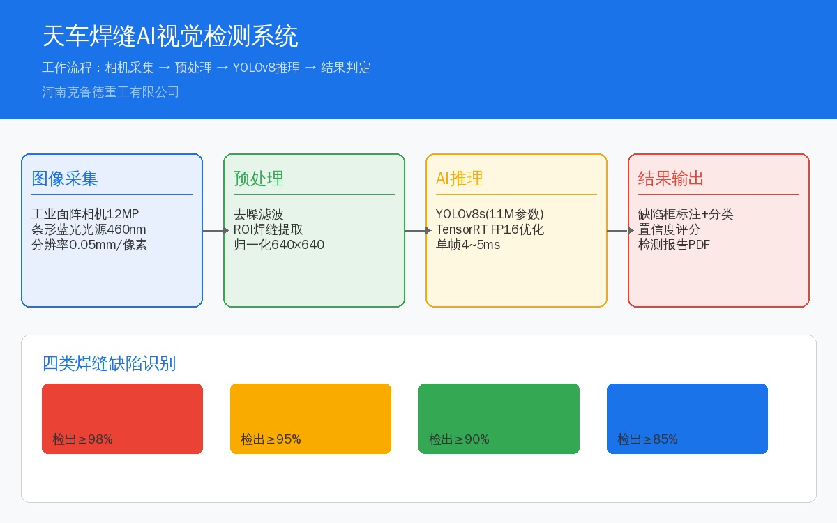
System Architecture for Vision-Based Weld Inspection
The AI weld inspection system follows a pipeline architecture, where each stage processes data and passes it on to the next module:
| Module | Function | Equipment Selection | Output |
|---|---|---|---|
| Image Acquisition | Weld Seam Area HD Imaging | Industrial Area Scan Camera+Bar Light Source | 1920×1080@30fps Raw Image |
| Image Preprocessing | Denoising+Enhancement+ROIExtraction | GPU/Olive Accelerated Preprocessing Pipeline | Normalized640×640Input |
| AIInference | Defect Target Detection+Classification | YOLOv8s + Tensor RT | Defect Bounding Box+Class+Confidence Score |
| Result Post-processing | Defect Annotation+Report Generation | Open CVRendering+PDFExport | Detection Report+Alarm Signal |
Industrial Cameras and Lighting Systems for Weld Inspection
The hardest part of weld inspection isn't the AI model—it's capturing a usable image in the first place. Overhead crane weld seams are covered in slag, spatter, and mill scale. A standard camera produces low-contrast, glare-heavy images, and no amount of AI can compensate for that.
Camera Selection: We recommend a 12MP industrial area scan camera (4096×3000) with a 3.45μm pixel size and a rolling shutter. Pair it with a 25mm fixed focal length industrial lens. At a working distance of 300mm, the field of view is approximately 200×150mm, yielding a single-pixel resolution of about 0.05mm—at this resolution, a 0.5mm crack spans 10 pixels, which is more than enough for reliable AI identification. Frame rate isn't critical here; 15fps is sufficient since weld inspection is a stop-and-check operation, not continuous tracking.
Lighting Setup: Weld surfaces are textured, so structured light or low-angle bar lighting is needed to bring out defects. We recommend a blue bar light source (460nm wavelength) at a 30° illumination angle, paired with a narrow-band filter of the same wavelength to effectively block arc flash interference. A complete lighting kit with controller runs approximately $450–$750—it's the component most likely to be underestimated, yet it's absolutely indispensable.
| Component | Recommendation Model/Specification | Unit Price | Application |
|---|---|---|---|
| industrial camera | Hikvision MV-CA050-10GM 12MP | Approx.3500CNY | High Resolution Area HD Imaging |
| Industrial Lens | Computar M2514-MP2 25mm/F1.4 | Approx.1200CNY | Fixed-focal Imaging |
| Bar Light Source | OPT-LI460200-W Blue Bar | Approx.3000CNY | Low Angle Illumination Highlighting Defect |
| Bar Light Source Controller | OPT-DPAS24-2 Two-channel Analog | Approx.2000CNY | Constant-current Dimming |
| Narrow Bandpass Filter | 460nm±10nm BP | Approx.500CNY | Arc Glare Rejection |
| industrial PC | Advantech MIC-770 + RTX4060 | Approx.12000CNY | AIInference+Control |
AI Model Training and Deployment
3.1 Dataset Construction
For non-destructive testing of welds on overhead cranes, the dataset is built from two sources: real defect images captured on the manufacturing floor (highly valuable but limited in quantity) and synthetic defect images generated through data augmentation (to supplement the sample size). A hybrid approach is recommended: 500–1,000 real images combined with augmented synthetic images to reach 3,000–5,000 total samples.
Defects are classified into four categories in accordance with the ISO 4306 standard for non-destructive testing of welds:
| Defect Type | Typical Characteristics | Hazard Grade | AIDetection Rate Requirement |
|---|---|---|---|
| Crack(Crack) | Elongated Dark Line, Sharp Edge | High Risk | ≥98% |
| Porosity(Porosity) | Circular/Elliptical Dark Spot, Isolated or Clustered | Medium Risk | ≥95% |
| Undercut(Undercut) | Along Weld toe Groove, Parent Metal Depression | Medium Risk | ≥90% |
| Overlap(Overlap) | Weld Seam Metal Overflow onto Base Metal Surface | Low Risk | ≥85% |
For annotation, LabelImg or CVAT is recommended. Each annotated image is exported in YOLO format (class + center x + center y + width + height, all normalized to 0–1).
3.2 Model Selection and Training
YOLOv8s (small version, ~11M parameters) is recommended for the best balance between accuracy and speed. Training configuration:
from ultralytics import YOLO # Load Pretrained Model type model = YOLO("yolov8s.pt") # Training(RTX4060Approx.3Hours to Complete300epoch) results = model.train( data="weld_dataset.yaml", epochs=300, imgsz=640, batch=16, lr0=0.01, augment=True, device=0 # GPU ) # Validation metrics = model.val() print(f"mAP@0.5: {metrics.box.map50:.3f}") print(f"mAP@0.5:0.95: {metrics.box.map:.3f}")After training, TensorRT is used to optimize inference speed: YOLOv8s achieves an original inference latency of ~12ms on an RTX 4060, which drops to 4–5ms after TensorRT FP16 optimization. With 4 cameras polling in sequence, a single inference cycle stays under 35ms, meeting the real-time requirements of online detection.
# TensorRTExport model.export(format="engine", dynamic=True, half=True) # Inference import tensorrt as trt import pycuda.driver as cuda engine = trt.Runtime(trt.Logger()).deserialize_cuda_engine( open("yolov8s_weld.engine", "rb").read()) # Single-Frame Inference Time Approx.5ms (RTX4060)4. Deployment of the Online Detection System
The system is installed at the end-of-line station of the crane main girder welding production line. Once welding is complete, the main girder automatically moves to the inspection station, where industrial cameras capture images of the four main weld seams (two on the top cover plates and two on the bottom cover plates). Each weld seam is photographed in 3–5 images covering its full length, and the AI automatically detects and marks defect locations.
Deployment parameters:
| Parameter | Value | Description |
|---|---|---|
| Detection Cycle Time | ≤15s/pcs Main Girder | Incl. Image Acquisition+Inference+Report |
| minimum Detectable Defect 0.3mm width | Crack Line-like Defect | |
| detection accuracy | m AP@0.5 ≥ 92% | 4 Categories Defect Average |
| False Positive Rate | ≤5% | Weld Slag/Spatter-induced False Alarm |
| Operating Temperature | 0~50°C | Industrial Environment Rated |
| Data Storage | ≥3years | Defect Raw Image+Detection Recording |
5. Key Implementation Considerations
1. Lighting beats the model. This is the first rule of machine vision. During our initial trial run, we used a standard ring light, which caused severe glare on the weld seam and made cracks impossible to capture. For a broader look at overhead crane fault diagnosis, see our earlier article on crane predictive maintenance and PHM system solutions. No matter how capable the YOLOv8 model is, it cannot detect what the camera cannot see. After switching to a low-angle blue bar light, defect contrast improved by more than 3×, and model mAP jumped from 68% to 89%. Lighting accounts for less than 10% of the total system cost but drives roughly 80% of the detection performance.
2. What to do when defect samples are scarce. Limited real-world defect samples are a common challenge across all industrial vision projects. Our approach: first, we created artificial defects by machining test plates with Wire EDM and collected 500 images to train an initial model. After deployment, we used this model for pre-screening, then manually confirmed the results and fed real defect images back into the training set for iterative improvement. After three iteration cycles, model performance on real data surpassed that of the version trained solely on simulated defects.
3. Balancing false positives and missed detections. The visual characteristics of weld reinforcement and undercut overlap with spatter, so false positive rates are inherently higher than for cracks. Our engineering strategy: cracks and porosity are assigned a high confidence threshold (≥0.7) and automatically flagged as non-conforming; undercut and weld reinforcement use a lower threshold (≥0.4) and are marked as "pending manual review." This ensures high-risk defects are never missed while preventing operator fatigue from excessive false alarms.
4. Integrating with the production line PLC. The inspection system outputs a discrete signal to the PLC (via Modbus TCP or digital I/O), triggering an alarm light and conveyor stop when cracks or porosity are detected. Inspection reports in XML format are uploaded to the MES system via FTP for archival. No changes to the existing PLC program are required—the inspection system operates as a standalone device that simply outputs an OK/NG signal.
5. Regular calibration is essential. Camera and lighting degradation can compromise detection consistency. We recommend running a calibration routine monthly using a standard reference plate (a test plate with known defects). If three consecutive calibration results deviate from the standard by more than 10%, the system automatically prompts recalibration or light source replacement.
Final Thoughts
AI-based visual weld inspection is not new—automotive manufacturing and pipeline industries have used it for years. What makes the overhead crane industry unique is the long weld seams (a 30-meter main girder has four longitudinal welds), complex surface conditions (heavy spatter), and defect acceptance criteria referenced to ISO 5817 (formerly GB/T 3323). Once these conditions are properly adapted, AI vision performs on par with human inspectors on crane weld inspection, while delivering significantly higher efficiency and consistency.
We ran a six-month field trial on a 32-ton bridge crane main girder welding line: 286 weld seams were inspected, AI detected 17 crack-type defects (including 2 missed during initial manual inspection), achieving an overall detection rate of 94.6% with an average inspection time of 12 seconds per weld seam. Our next step is to integrate inspection data into the crane digital twin platform to correlate weld defect records with structural health monitoring data for each crane throughout its service life.
Frequently Asked Questions
Q: Can AI weld inspection replace manual flaw detection?
A: Not entirely, but it can significantly reduce manual workload. AI vision inspection primarily performs rapid surface defect screening (cracks, porosity, undercut, weld reinforcement) with a detection rate above 92%. For internal defects (lack of fusion, slag inclusion, etc.), ultrasonic or radiographic testing (RT) is still required. The recommended workflow: AI performs 100% rapid screening → AI-flagged suspicious areas are prioritized for manual flaw detection → unmarked areas undergo sampling inspection. This approach reduces manual inspection workload by approximately 70%.
Q: What production line modifications are required for this system?
A: An inspection station needs to be added at the end of the crane main girder welding line, including a camera mounting frame (approximately 1.5m × 1.5m gantry frame), light source mounting bracket, and an industrial PC cabinet. The camera is fixed-mounted approximately 300mm from the weld surface—no motion mechanism is needed (the main girder stops on the roller conveyor at the inspection station for imaging). Electrically, an AC220V power outlet and LAN connection are required. Total production line retrofit cost (including installation & commissioning) is approximately $1,500–$4,500.
Q: Can welds with surface corrosion or paint still be inspected?
A: Yes, but accuracy will be affected. If the AI model was trained with corroded/painted samples, detection accuracy drops by approximately 5–10 percentage points. We recommend performing weld inspection before painting—this is already an existing process step in crane manufacturing (welding → weld inspection → painting), so no production flow changes are needed. For in-service crane repair welds, the weld surface can be ground before imaging.
