
An In-Depth Technical Analysis of Crane Automation Control Systems
I. Overview of the Crane Automation Control System Architecture
The crane automation control system serves as the ”brain” and ”nervous system” of a smart crane. A typical control system employsThree-tier architecture: Perception layer (sensors + encoders), control layer (PLC + variable-frequency drive), and execution layer (motors + brakes). The three layers are connected viaIndustrial Ethernet Bus(PROFINET, EtherCAT, or Modbus TCP) real-time communication, with a control cycle typically ≤10 ms.
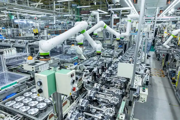
▲ Topology of a Crane Automation Control System
II. Analysis of the Core Control Module
1. Selection and Configuration of the Main PLC
The crane's main control PLC must meet the following requirements:High-Speed Counting(Encoder signals above 10 kHz),Safety Redundancy(Dual-CPU hot standby) andAdaptation to Harsh Environments(Protection rating IP54 or higher; operating temperature -20°C to +60°C). Popular options include the Siemens S7-1500 series, the Mitsubishi Q series, or the Beckhoff CX series.
2. Variable-Frequency Drive System
Hoisting Mechanism RequirementsFour-Quadrant Operation(Hoisting/Lowering/Acceleration/Braking): It is recommended to use a variable-frequency drive (VFD) equipped with an AFE rectifier unit. Since the main and auxiliary hoist mechanisms have lower dynamic response requirements, an economical vector VFD may be selected. A multi-drive configuration (with a common DC bus) enables energy sharing—regenerative energy from braking equipment is directly absorbed by accelerating equipment, improving the system’s overall energy efficiency by 10%-15%.
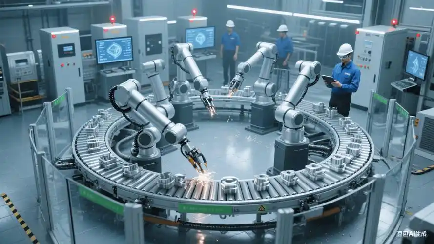
▲ Programming and Debugging of Crane PLC Control Systems
3. Encoders and Position Detection
Position detection accuracy directly affects the precision of automated operations. The lifting height and the positions of the hoist and trolley are determined byAbsolute Encoder(SSI interface, resolution ≥ 13 bits), ensuring that position data is not lost after a power outage. For applications requiring high positioning accuracy, you can installLaser Rangefinder(Accuracy: ±2 mm) orGray Busbar(Accuracy: ±5 mm) as a redundant positioning method.
4. Safety PLCs and Functional Safety
According to the ISO 13849 standard, the safety level of crane control systems must meetPL dLevel. The safety PLC operates independently of the main PLC and monitors overspeed, overload, limit switch overtravel, and brake status in real time. If it detects that safety conditions are not met, it canWithin 100 msDisconnect the power supply and apply the emergency brake.
III. Communication Bus Technology
Modern crane control systems utilizeThree-Tier Network Architecture:
- Management (Ethernet):The host computer/scheduling system communicates with the PLC using the OPC UA or Modbus TCP protocol.
- Control Layer (Fieldbus):Real-time communication between the PLC, the variable-frequency drive, and the remote I/O uses the PROFINET IRT or EtherCAT protocol.
- Field Layer (Sensor Bus):Signal Transmission Between Encoders, Limit Switches, and the PLC
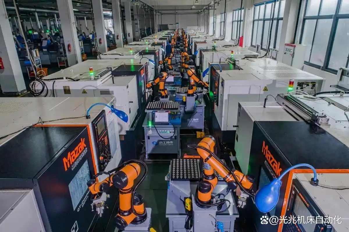
▲ On-site Commissioning and Testing of Automation Control Systems
IV. System Testing and Acceptance
- Standalone Debugging:Test the inverter parameters, encoder direction, and limit switch logic for each device separately.
- Online Debugging:PLC and Inverter Communication Testing, Input/Output Signal Mapping Verification
- Functional Testing:Verification of speed in each gear for hoisting, main travel, and trolley; brake timing synchronization
- Security Testing:Simulate faults such as overspeed, overload, and limit switch overtravel to verify the safety PLC's response
- Load Testing:Static load test at 1.25 times the rated load; dynamic load test at 1.1 times the rated load
Frequently Asked Questions
问:起重机自动化控制系统包含哪些层级?
A:四层架构:设备层(变频器/传感器/执行器)、控制层(PLC/运动控制器)、调度层(WMS/SCADA)、管理层(MES/ERP)。自动化程度越高,调度层和管理层的集成越关键。
问:起重机自动化改造的投入产出周期?
A:一般改造投入回收周期1~3年。主要收益包括:减少操作人员50%~70%、提高作业效率20%~40%、降低故障停机时间30%~50%、提升安全水平。
问:自动化改造执行哪些标准?
A:控制系统按GB/T 3811和GB 5226.2,安全符合GB 6067和GB/T 28264,通信参考OPC UA(IEC 62541)。
