

Overhead Crane Hoisting Mechanism & Wheel Block Design
Overhead Crane Hoisting Mechanism & Wheel Block Design: Per ISO 4301, the drum diameter is calculated using D ≥ (h₁×h₂)×d, where the coefficient is 16 for Work Duty M5 and 20 for M6, multiplied by the wire rope diameter. Wheel treads are recommended in ZG50Mn2 with medium-frequency quenching to HB350–450. The hoisting mechanism must be equipped with two independent brakes—one on the high-speed shaft and one on the low-speed shaft—to meet mandatory safety requirements.
The overhead crane hoisting mechanism is the core actuation system responsible for lifting and moving loads. It consists of the drum assembly, pulley block, reducer, and brake system. The wheel block, in turn, provides the load-bearing foundation for crane travel. This article references ISO 4301 to systematically break down drum diameter calculation and wall-thickness verification, pulley selection and wear criteria, and wheel material and heat-treatment processes—delivering complete design parameters and engineering data.
Drum Assembly Design for Overhead Cranes
The drum is the core rotating component in the hoisting mechanism that spools the wire rope and transmits driving force. Drum diameter is calculated per ISO 4301 using the formula D ≥ (h₁×h₂)×d, where h₁ is a coefficient tied to the work duty classification (16 for M5, 20 for M6), h₂ is a coefficient related to wire rope construction (1.0 for alternate lay), and d is the wire rope diameter. A larger drum diameter reduces bending stress on the rope and extends its service life, but it also increases drum size and dead weight. In practice, engineers typically select the smallest diameter that still satisfies the coefficient requirements to minimize the crane's overall weight.
| Parameter | Value / Requirement |
|---|---|
| Drum diameter formula | D ≥ (h₁ × h₂) × d |
| h₁ (work duty coefficient) | 16 for M5, 20 for M6 |
| h₂ (rope construction coefficient) | 1.0 for alternate lay |
| d | Wire rope diameter (mm) |
The drum wall thickness must be verified for both compressive stress and torsional stiffness. For welded drums, the wall thickness typically ranges from 15 to 25 mm depending on the drum diameter and the rope pull force. The drum groove profile must match the wire rope diameter, with groove depth and pitch designed to prevent rope overlap and ensure smooth spooling. The drum ends are usually fitted with flanges to retain the rope, and the entire assembly is mounted on bearings that support both radial and axial loads during operation.
Pulley Selection and Wear Limits
Pulleys in the hoisting mechanism redirect the wire rope and provide mechanical advantage. The pulley diameter is also governed by the D ≥ (h₁×h₂)×d formula, but with different h₁ values compared to the drum—typically 14 for M5 and 16 for M6. The pulley groove must be machined to match the rope diameter, with a groove radius slightly larger than the rope radius to reduce contact pressure and wear.
Pulley wear is a critical maintenance parameter. The groove wear limit is generally set at 25% of the original groove depth; beyond this point, the pulley must be replaced or re-machined. The tread surface hardness should be in the range of HB300–380 for cast steel pulleys, achieved through heat treatment. The pulley block assembly includes the pulley, bearings, and a shaft, all designed to handle the rated load with an appropriate safety factor.
Wheel Block Materials and Heat Treatment
The wheel block is the load-bearing component that enables crane travel along the runway rails. Wheel treads are subjected to high contact stress and wear, making material selection and heat treatment critical for service life. The recommended material is ZG50Mn2 cast steel, with medium-frequency induction quenching to achieve a tread surface hardness of HB350–450. This heat-treatment process creates a hardened wear layer while maintaining a tough core to resist impact loads.
The wheel tread profile must match the rail head to ensure uniform contact pressure and minimize wear. The wheel diameter is selected based on the maximum wheel load and the allowable contact stress between the tread and the rail. For standard overhead cranes, wheel diameters typically range from 250 mm to 1,000 mm, depending on the crane capacity and span. The wheel block assembly includes the wheel, axle, bearings, and mounting brackets, all designed to transmit the crane's dead weight and rated load to the runway.
Braking System Requirements for Hoisting
The hoisting mechanism must be equipped with two independent braking systems: one on the high-speed shaft (motor shaft) and one on the low-speed shaft (drum shaft). This dual-brake configuration is a mandatory safety requirement under ISO 4301, ensuring that the load remains suspended even if one brake fails. The high-speed shaft brake is typically a disc brake or a shoe brake that provides rapid deceleration, while the low-speed shaft brake is usually a drum brake that holds the load stationary.
Brake selection is based on the braking torque required, which is calculated from the hoisting load, the drum diameter, and the overall gear ratio. The braking torque must be at least 1.5 times the static torque of the suspended load to ensure reliable holding. The brake lining material must have a high friction coefficient and good wear resistance, with heat dissipation capacity sufficient for frequent start-stop cycles.
Design Standards and Compliance for Overhead Cranes
All design parameters for the hoisting mechanism, wheel block, and braking system must comply with ISO 4301, which aligns with the international standard ISO 4301 for crane classification and design. The work duty classification (M5, M6, etc.) determines the coefficients used in the drum and pulley diameter calculations, as well as the fatigue life requirements for all load-bearing components. Compliance with these standards ensures that the crane operates safely throughout its design life under the specified duty cycle.
In addition to the design standard, the electrical and control systems must comply with IEC 60204-32, which covers the safety requirements for crane electrical equipment. This includes overload protection, limit switches, and emergency stop functions. The entire crane system must undergo rigorous testing and inspection before commissioning, including load tests at 125% of the rated capacity to verify structural integrity and braking performance.
| Work Duty / Classification | h₁Coefficient | Recommended D/d Ratio |
|---|---|---|
| A3~A4(Light Duty) | 14 | ≥14×d |
| A5(Medium Duty) | 16 | ≥16×d |
| A6(Heavy Duty) | 18 | ≥18×d |
| A7~A8(Extra Heavy Duty) | 20 | ≥20×d |
| Wire Rope Diameter | Recommended Drum Wall Thickness |
| 6 mm | 8 mm |
| 8 mm | 10 mm |
| 10 mm | 12 mm |
| 12 mm | 14 mm |
| 14 mm | 16 mm |
| 16 mm | 18 mm |
| 18 mm | 20 mm |
| 20 mm | 22 mm |
| 22 mm | 25 mm |
| 24 mm | 28 mm |
| 26 mm | 30 mm |
| 28 mm | 32 mm |
| 30 mm | 35 mm |
| 32 mm | 38 mm |
| 36 mm | 42 mm |
| 40 mm | 45 mm |
The table below provides a quick drum selection guide based on wire rope diameter, including recommended wall thickness:
| wire rope diameter | A5drum diameter | A7drum diameter | Cast Iron Wall Thickness | Cast Steel Wall Thickness |
|---|---|---|---|---|
| ∅14mm | ∅224mm | ∅280mm | 16mm | 12mm |
| ∅18mm | ∅280mm | ∅355mm | 18mm | 14mm |
| ∅22mm | ∅355mm | ∅450mm | 22mm | 16mm |
| ∅28mm | ∅450mm | ∅560mm | 28mm | 20mm |
| ∅32mm | ∅500mm | ∅630mm | 32mm | 24mm |
| ∅36mm | ∅560mm | ∅710mm | 36mm | 26mm |
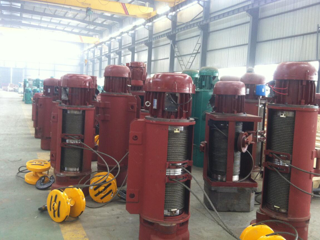
Drum strength verification is primarily governed by the wall compressive stress. For a 50t overhead crane (∅28mm wire rope, drum ∅560mm, wall thickness 20mm, material ZG270-500, maximum tension 130kN), the wall compressive stress is approximately 92.5MPa, with an allowable stress of 125MPa (safety factor of 4), yielding a safety margin of 26%. Rope groove parameters per ISO 4301 Crane Design Standard: groove bottom radius R=(0.53~0.56)×d, groove depth h≥0.35×d, and pitch s=d+(2~4)mm.
Pulley Block Design and Sizing
The sheave diameter D_sheave must satisfy D_sheave ≥ (h₃×h₂)×d, where the h₃ coefficient is: 16 for duty class A3~A4, 18 for class A5, 20 for class A6, and 22.4 for class A7~A8. Quick selection examples: a ∅14mm rope pairs with a ∅280mm sheave (class A5), a ∅28mm rope with a ∅560mm sheave, and a ∅32mm rope with a ∅630mm sheave.
Recommended sheave materials: cast iron HT200 for duty classes below A5 (cost-effective), and cast steel ZG270-500 for classes above A6 (high strength, impact-resistant). For high-speed overhead cranes, rolled steel sheaves offer a lightweight design advantage. Spherical roller bearings are recommended for sheave applications—their self-aligning capability resists off-axis loads. Lubrication is required once a month, with a service life of 5,000 to 10,000 hours. Sheave rope groove wear limits: replace the sheave if the groove bottom radius wears beyond 20% of its original dimension or if the groove wall thickness wears by more than 20%. Radial runout exceeding 1mm can be corrected by turning.
Wheel Block Design and Material Selection
An overhead crane wheel block consists of the wheel, an angled bearing housing, and the wheel shaft. The wheel material directly affects load capacity and service life, with heat treatment being the critical factor in achieving the required wear resistance.
| Component | Recommended Material | Heat treatment Method | Hardness Requirement | Hardened Case Depth |
|---|---|---|---|---|
| Wheel Tread | ZG50Mn2/ZG50MnMo | Surface Hardening(Medium Frequency/Flame) | HB 350~450 | 10~20mm |
| Wheel Flange | ZG50Mn2/ZG50MnMo | Surface Hardening | HB 300~380 | 8~15mm |
| Gear Tooth Flank | 40Cr/42CrMo | Tooth Flank Quenching/Carburizing | HRC 50~58 | 1~2mm |
| Gear Core | 40Cr/42CrMo | Quenched and Tempered | HB 250~300 | Throughout |
| Drum | ZG270-500 | Normalizing+Tempering | HB 160~220 | Throughout |
| Pulley | HT200/ZG270-500 | Stress Relieving Annealing | — | — |
The wheel tread surface is hardened by medium-frequency surface hardening to achieve a hardness of HB 350–450, with a hardened layer depth of 10–20 mm, enabling it to withstand the contact stress between the wheel and the crane rail. The wheel flange hardness is HB 300–380, slightly lower than the tread to reduce the risk of crack propagation during wear. Gear tooth surfaces undergo carburizing and quenching to reach a hardness of HRC 50–58, while the core is quenched and tempered to HB 250–300 to maintain toughness. Wear detection on wheels can draw on the experience of online crane wire rope inspection technology (see Crane Wire Rope Inspection Technology).
Brake Configuration for Hoisting Mechanisms
Safety braking for hoisting mechanisms is a mandatory requirement under ISO 4301 Crane Design Standard. The hoisting mechanism must be equipped with two independent brakes—one on the high-speed shaft (motor shaft end) and one on the low-speed shaft (drum end). The high-speed shaft brake handles normal operational braking, while the low-speed shaft safety brake serves as the second line of defense for emergency braking and preventing load drops. For hoisting mechanisms rated A6 and above, hydraulic thrust brakes are recommended, with braking torque designed at 1.5 times the rated load.
Regular brake inspection and maintenance can be supported by real-time monitoring through the overhead crane digital remote monitoring platform (see Overhead Crane Digital Remote Monitoring Solution). Predictive maintenance is achieved by tracking parameters such as brake actuation count, braking time, and brake temperature rise.
Kelude Heavy Industry Mechanical Component Solutions
Kelude Heavy Industry supplies a full range of overhead crane mechanical components, including drum assemblies (HT200/ZG270-500/Q345B welded drums), pulley blocks (HT200/ZG270-500/rolled steel pulleys), wheel blocks (ZG50Mn2/ZG50MnMo surface-hardened), reducers, couplings, and brakes. All components are manufactured in compliance with ISO 4301 Crane Design Standard and GB/T 10051, with complete strength verification calculation reports and heat treatment process documentation provided. Kelude Heavy Industry offers free technical consultation and component selection services.
Frequently Asked Questions
Q: How do I select the right drum assembly for an overhead crane hoisting mechanism?
A: The drum diameter is typically 20–30 times the wire rope diameter, and the drum length is calculated based on the lifting height and the pulley ratio. Common drum materials are Q235B (≈S235JR) or Q355B (≈S355JR); for heavy-duty applications, ZG270-500 cast steel is used. The drum wall thickness must be verified for strength in accordance with ISO 4301 Crane Design Standard.
Q: How do I choose the right material for overhead crane wheel blocks?
A: Common wheel materials include ZG340-640, ZG35CrMo, and 42CrMo. For duty classifications below A5, ZG340-640 is recommended; for A6 and above, ZG35CrMo with quenching and tempering is preferred. The wheel tread hardness must reach HB 300–380 to ensure adequate wear resistance.
Q: Which standards apply to hoisting mechanism design?
A: Design follows ISO 4301 Crane Design Standard, with drums per JB/T 9005.1, pulleys per JB/T 9005.2, and wheels per JB/T 6392.
