

Crane Rail & Main Girder Design: QU Rail, Box Girder Standards
Crane Rail & Main Girder Design Selection: Per ISO 4301, QU70–QU120 rails are matched by capacity (≤10t → QU70; 200t+ → QU120). Box girders are the preferred option, with a section width-to-height ratio of 1:12–1:16 and a camber of F = S/1000. Aluminothermic welding is recommended for rail joints; A7/A8 duty classes require 100% Ultrasonic Testing (UT) and Magnetic Particle Inspection (MPI).
The crane rail system is the foundation of safe overhead crane operation. Rail selection and installation accuracy directly determine ride smoothness, positioning accuracy, and service life. As the load-bearing core, the main girder's section profile, camber, and welding process are equally critical to overall performance. This article references ISO 4301 and GB/T 10183-2023 to provide a systematic breakdown of crane rail selection, box-girder design, and welding best practices.
Crane Rail Selection: QU vs. P-Type Rails Compared
Crane rails fall into two main categories by section profile: QU-type (crane-specific rails) and P-type (railway rails). QU-type rails, manufactured to YB/T 5055-2014, feature a thickened head and superior wear resistance, making them ideal for overhead cranes in A5 and heavier duty classifications. P-type rails, produced to GB/T 2585-2021, offer a lower cost alternative suited to A5 and lighter duty applications.
Rail Selection Reference Table
| overhead crane Capacity | Recommended rail | rail height | Per Meter Weight | Mounting Type |
|---|---|---|---|---|
| ≤10t | P38 / QU70 | 134mm / 120mm | 38kg/m / 52kg/m | Clamping Plate Fixing |
| 16-32t | QU70 / QU80 | 120mm / 130mm | 52kg/m / 63kg/m | Clamping Plate Fixing |
| 50-80t | QU80 / QU100 | 130mm / 150mm | 63kg/m / 88kg/m | Clamping Plate+Welding |
| 100-160t | QU100 / QU120 | 150mm / 170mm | 88kg/m / 118kg/m | Welding+Bolt |
| 200t+ | QU120 | 170mm | 118kg/m | Welding+Bolt |
When selecting, pay attention to the work duty classification: for overhead cranes rated at A6 or higher, QU-series crane rails are the preferred choice. If abnormal wheel wear or skewing occurs during operation, refer to Crane Rail Gnawing Diagnosis for targeted troubleshooting.
Crane Rail Installation Tolerances & Joint Techniques
Rail installation must comply with the tolerance ranges specified in ISO 12480 (formerly GB/T 10183-2023). Below are the key installation acceptance indicators:
Rail Installation Tolerance Table
| Detection Item | Tolerance Requirement |
|---|---|
| Crane Rail Centerline to Datum Line Deviation | ±3mm(crane runway girder Full Length) |
| Crane Rail Span Deviation(Span≤30m) | ±5mm |
| Crane Rail Span Deviation(Span>30m) | ±8mm |
| Rail Top at Same Section in Same Span Elevation Deviation | ≤10mm |
| Per Unit Length Along10mElevation Deviation | ±5mm |
| Rail Joint Clearance | 1-3mm(Per50°CTemperature Differential Calculation) |
| Rail Joint Elevation Difference | ≤1mm |
| Rail Joint Lateral Offset | ≤1mm |
| Two Rails Crane Rail Relative Elevation(Same Section) | ≤10mm |
Crane rail joints fall into three categories: butt joints with straight gaps suit P-type rails and light-duty overhead cranes, with a 1–3 mm gap secured by fishplates; 45° diagonal butt joints are recommended for QU-type rails on heavy-duty cranes, reducing wheel impact when crossing the joint; welded butt joints are used for QU100 and heavier rails as well as long welded rail layouts — preheating to 150°C or above is required before welding, followed by slow cooling after welding.
Standard spring clamp plate spacing is 500–700 mm, tightened to 300–500 mm through curves. Bolted clamp plates are recommended for easier shaft alignment during maintenance; high-speed cranes may use spring clamp plates for improved vibration damping.
Main Girder Design: Box Girder as the Preferred Choice
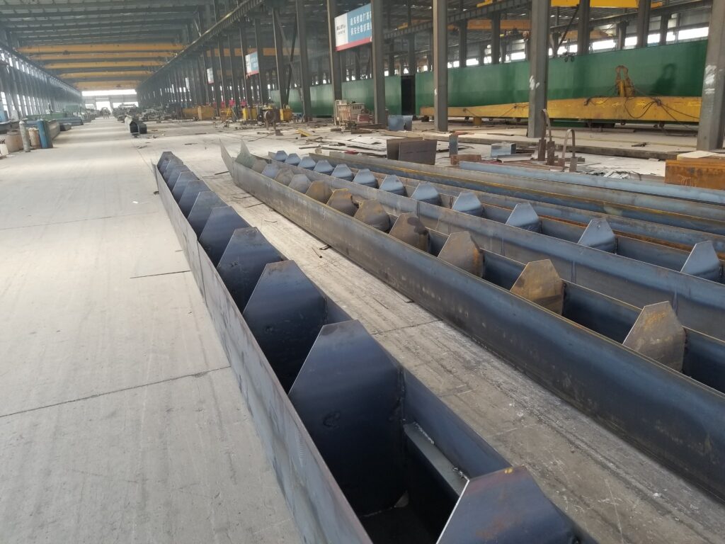
The main girder is the primary load-bearing structure of any crane. When comparing box girders against truss girders, the box girder — with its closed-section torsion resistance and superior fatigue performance — is the preferred choice for general-purpose overhead cranes, particularly for duty classifications A5 through A8.
Key design parameters for box girders: section width-to-height ratio of approximately 1:12 to 1:16, top flange plate 6–8 mm thick, bottom flange plate 8–10 mm thick, and web plates 5–6 mm thick. The main girder must be fabricated with a parabolic camber, with the standard value set at F = S / 1000 (where S is the span). Mid-span camber tolerance is +0.3F / −0.1F. In static load testing, no permanent deformation is permitted under 1.25 times the rated load; deflection under rated load must not exceed: S/500 for duty classes A1–A3, S/700 for A4–A6, and S/800 for A7–A8.
End carriages are typically welded box structures rigidly connected to the main girder. Wheel assemblies use angular bearing housings, with individually driven wheels and VFD control as the preferred arrangement. To further optimize crane performance, see our crane VFD speed control solutions.
Crane Rail Welding Procedures and Acceptance Standards
For heavy rail welding, aluminothermic welding is the preferred method — efficient and well suited to field conditions; QU120 heavy rails may also be joined by gas pressure welding. The aluminothermic welding agent must match the rail profile (QW-QU70/80/100/120). Preheating temperature: 350–450°C (≥400°C in winter); welding time: 20–40 s; mold retention: ≥5 min; upsetting temperature: ≥850°C. Ambient temperature must be ≥5°C (no work below 0°C), wind speed ≤5 m/s, and relative humidity ≤80%.
Weld acceptance is governed by GB/T 10183-2023 and TB/T 1632-2014: weld reinforcement must be 100% of the profile with no porosity, slag inclusion, or cracks; rail head reinforcement ≤2 mm; web/base reinforcement ≤3 mm; straightness ≤0.5 mm/m; vertical and horizontal misalignment at joints ≤0.5 mm. Cranes in duty classes A7/A8 require 100% Ultrasonic Testing (UT) and Magnetic Particle Inspection (MPI); sampling rates are 30% for class A5 and 50% for class A6.
Rail Wear Detection and Replacement Intervals
Rail wear detection frequency is determined by duty classification: every six months for classes below A5, quarterly for A6–A7, and monthly for A8. A rail must be replaced when any of the following criteria are met: vertical head wear exceeding 8 mm for QU80 and lighter rails, or 10 mm for QU100 and above; side wear reducing head width by more than 5 mm; head cracks longer than 3 mm; or straightness exceeding 1.5 mm/m. Typical replacement intervals are 10–15 years for light duty (class A5), 3–5 years for heavy duty (class A7), and only 2–3 years for very heavy duty (class A8).
Summary
Crane rail and main girder design selection involves rail profile matching, installation tolerance control, box girder section optimization, camber specification, and welding procedure qualification. Selection must account for crane capacity, duty classification, span, and site conditions, in strict compliance with ISO 4301, YB/T 5055-2014, and related standards. Sound structural design not only ensures operational safety but also extends equipment service life and reduces maintenance costs.
Kelude Heavy Industry's crane structural design team brings over a decade of experience, offering end-to-end technical services from rail selection calculations and main girder finite element analysis to Welding Procedure Qualification Records (WPQR) — helping customers build efficient, safe, and durable overhead crane systems.
Frequently Asked Questions
Q: How do I select the right QU-series crane rail?
A: QU-series rails are classified by weight: QU70, QU80, QU100, and QU120. For light duty, QU70 is recommended; medium duty, QU80; heavy duty, QU100; and very heavy duty, QU120. Rail selection must account for lifting capacity, duty classification, and wheel load calculations.
Q: What are the key welding requirements for box girders?
A: Main welds on box girders should use submerged arc welding, with preheating (Q355B ≥100°C). Butt welds require 100% UT inspection; fillet welds are sampled per GB/T 11345. Post-weld stress-relief annealing is applied to control main girder camber and side bow.
Q: Which standards govern crane rail installation?
A: Rail installation follows GB/T 10183, "Tolerances for manufacture and rail installation of overhead and gantry cranes," with track gauge deviation ≤±5 mm and vertical misalignment at rail joints ≤1 mm.
