

Crane Gearbox Noise & Vibration: 5 Sound Checks & 7 Repair Standards
Abnormal noise and vibration in a crane gearbox are among the most common fault signals encountered during routine maintenance. Noise typically originates from poor gear meshing, bearing wear, coupling misalignment, or insufficient lubrication, while abnormal vibration is often linked to shaft bending, loose anchor bolts, or resonance in the drive system. Drawing on the ISO 4301 Crane Design Standard and extensive field experience, Kelude Heavy Industry has developed a diagnostic method covering 5 distinct noise signatures and 7 vibration maintenance criteria. This approach enables maintenance crews to quickly pinpoint the fault source without stopping the crane, cutting overhaul downtime by more than 50%.
The fault diagnosis and maintenance criteria discussed in this article are based on the gearbox load capacity and work duty design requirements of ISO 4301 Crane Design Standard, as well as the vibration testing and load test acceptance criteria of FEM 1.001 Crane Test Specification, providing a standard basis for on-site troubleshooting.
How to Diagnose Crane Gearbox Noise by Listening for 5 Sound Signatures
Abnormal noise from a crane gearbox is the easiest early warning sign for maintenance crews to catch. A healthy gearbox produces a steady, low hum from gear meshing, typically not exceeding 85 dB(A). When any of the following five abnormal sound signatures appear, the likely fault location and severity can be assessed by listening:
1. High-frequency whine – A sharp, piercing screech, typically in the 1 kHz to 4 kHz range, increasing with rotational speed. This usually indicates insufficient tooth surface lubrication or oil film breakdown, causing direct metal-to-metal contact. Kelude service data shows that roughly 35% of gearbox noise faults stem from poor lubrication.
2. Rhythmic clicking – A regular knocking sound whose frequency is proportional to shaft speed. Common causes include pitting, spalling, or tooth fracture on the gear flank, producing one impact per revolution. Similar sounds can arise from pitting or spalling on bearing raceways or rolling elements; frequency analysis can distinguish gear-related from bearing-related sources.
3. Dull rumbling – A low-frequency, continuous rumble accompanied by noticeable housing vibration. This is usually caused by excessive gear backlash or severe tooth wear, especially when backlash exceeds the standard limit of 0.5 mm. Gearboxes operating under A6 to A8 work duty classifications are more prone to this issue over time.
4. Intermittent squeaking – Irregular, sharp metallic scraping sounds. Common causes include a damaged bearing cage, stuck rollers, or foreign debris inside the housing. In severe cases, fragments from a fractured coupling element can enter the gear mesh zone.
5. Continuous grinding – A fine, persistent sand-like noise, low in volume but constant. This is often caused by contaminated lubricating oil (excessive moisture or metal particles) accelerating micro-motion wear on tooth surfaces. This sound is typically audible when wear particle concentration exceeds 500 ppm in oil analysis.
On-site listening can be enhanced using an industrial stethoscope or sound level meter paired with a spectrum analysis app to compare captured sound waveforms against fault characteristic frequencies. Kelude's technical service team recommends immediate shutdown for the first three sound types; the last two can be scheduled for planned maintenance, but no later than 48 hours after detection.
3 Spectrum Signatures of Gear Mesh Noise and Inspection Criteria
Gear mesh noise in industrial gearboxes can be precisely located using vibration spectrum analysis. The normal gear mesh frequency (GMF) is calculated as: GMF = number of teeth × shaft rotational frequency (Hz). For example, in a Kelude CD1-10t electric hoist gearbox running at 1400 rpm (23.3 Hz) with an 18-tooth primary pinion, GMF = 18 × 23.3 = 420 Hz. The following three spectrum signatures near this frequency indicate a fault:
Signature 1: Excessive GMF amplitude. When vibration velocity at GMF and its 2nd and 3rd harmonics exceeds 7.1 mm/s (ISO 10816-3 Zone C/D boundary), significant tooth wear or pitting is present, requiring gearbox opening for tooth surface inspection.
Signature 2: Dense GMF sidebands. Equally spaced sideband clusters appear around GMF (spacing equal to the faulted gear's rotational frequency), with sideband amplitude exceeding 30% of the GMF amplitude. This indicates gear eccentricity, pitch error, or shaft bending. Radial runout should be measured with a dial indicator; the allowable limit is 0.05 mm.
Signature 3: Non-integer harmonic impacts. Random impact signals in the spectrum that are not integer multiples of GMF, with a distinct pulse pattern in the time waveform, typically indicate a broken gear tooth or fractured bearing cage. This is an emergency shutdown condition – the gearbox must be taken out of service immediately.
Per ISO 4301, gear contact pattern under rated load must cover at least 45% along the tooth height direction and 60% along the tooth length direction. Standard backlash values are 0.10–0.20 mm for module 3–6 mm gears and 0.15–0.30 mm for module 6–10 mm gears. Failure to meet any of these criteria requires immediate gear set adjustment or replacement.
How to Identify Bearing Failure from Clicking Noise and Temperature Rise
Bearing failure is the second most common source of abnormal gearbox noise after gear faults, accounting for 28% of Kelude after-sales maintenance cases. Bearing faults can be diagnosed using three complementary dimensions: sound signature, temperature monitoring, and vibration parameters.
Sound signature: When pitting or spalling develops on the inner or outer ring raceway of a rolling bearing, a periodic impact sound is produced. The fault characteristic frequency can be calculated: inner ring fault frequency BPFI = 0.5 × n × (1 + d/D × cos α) × fr; outer ring fault frequency BPFO = 0.5 × n × (1 − d/D × cos α) × fr, where n is the number of rolling elements, d is the rolling element diameter, D is the pitch diameter, and fr is the shaft rotational frequency. If the measured "clicking" period matches the calculated value, the faulty bearing position is confirmed.
Temperature monitoring: A healthy rolling bearing should not exceed ambient temperature +40 °C, with an absolute maximum of 80 °C (per ISO 4301). Using an infrared thermometer or thermal imaging camera at the bearing housing, if the temperature exceeds these limits or the temperature difference between bearing housings on the same gearbox exceeds 15 °C, lubrication failure or accelerated wear is indicated.
Vibration parameters: Acceleration sensors should be mounted radially and axially on the bearing housing to measure vibration acceleration. A new bearing typically reads below 10 m/s² (RMS); light wear produces 10–20 m/s²; severe wear or cage damage exceeds 30 m/s². The acceleration envelope spectrum should also be checked for bearing fault characteristic frequencies and their harmonics.
Kelude recommends maintaining a per-bearing temperature and vibration trend log during routine inspections. If vibration values show an upward trend for three consecutive readings, or temperature rise exceeds 5 °C per week, replacement should be scheduled immediately.
How to Measure and Correct Periodic Vibration from Coupling Misalignment
Coupling misalignment is the third leading cause of periodic vibration in crane gearboxes, particularly in configurations using flexible pin couplings or diaphragm couplings between the motor and the gearbox high-speed shaft. Misalignment falls into two categories – parallel misalignment (radial offset) and angular misalignment (axial tilt) – which can be distinguished by their vibration spectrum signatures:
Parallel misalignment: The spectrum is dominated by the 2× rotational frequency (2X), with axial vibration relatively low and radial vibration relatively high. Vibration amplitude increases significantly with load and may be barely noticeable at no load. Kelude field experience shows that when the 2X amplitude exceeds 50% of the 1X amplitude, radial alignment should be checked.
Angular misalignment: The spectrum is dominated by the 1× rotational frequency (1X), with axial vibration noticeably higher than radial vibration. The axial vibration phase difference across the coupling is approximately 180°, which can be confirmed with dual-channel phase analysis. Angular misalignment is also often accompanied by abnormal wear and temperature rise in the coupling element.
Correction criteria: Using a laser alignment tool or dial indicator, the allowable radial deviation between the two shafts is 0.05 mm, and the angular deviation is 0.05 mm per 100 mm (equivalent to 0.03°). The correction procedure involves: loosening the motor anchor bolts, adding or removing shims under the motor base to adjust height, using jacking screws for horizontal adjustment, tightening the anchor bolts diagonally in two passes to the specified torque, and finally re-measuring to confirm the deviation is within tolerance.
Kelude CD/MD series electric hoists are factory-aligned to within 0.03 mm at the coupling. It is recommended to re-align and record alignment data after every major overhaul.
How to Detect Whining Noise from Lubrication Failure and Oil Deterioration
Insufficient lubrication is the leading cause of high-frequency whining in gearboxes and accounts for the largest share of the five abnormal noise types. Lubrication failure falls into three categories: low oil level (below the midpoint of the sight glass), oil deterioration (viscosity drop or contamination), and incorrect oil grade (viscosity mismatch).
Oil level check: After stopping the crane for 15 minutes, check the sight glass or oil dipstick. The oil level should be between 1/2 and 2/3 of the sight glass height. When oil is low, the gear teeth cannot form a complete oil film; a minimum film thickness of approximately 1 µm is required for hydrodynamic lubrication. Kelude recommends checking the oil level every 500 operating hours and replacing the lubricating oil every 2,000 hours or 6 months, whichever comes first.
Oil condition testing: Three quick tests should be performed on an oil sample. Viscosity is measured with a portable viscometer; kinematic viscosity at 40 °C should fall within the ISO VG220 to VG460 range (depending on the gearbox model). A viscosity drop exceeding 15% requires an oil change. Moisture content is determined using the Karl Fischer method or a crackle test; water content should be below 500 ppm, as excess moisture reduces oil film strength and promotes tooth micro-pitting. In ferrography/spectrometry analysis, iron content above 200 ppm or silicon content (dust contamination) above 50 ppm indicates the need for an oil change and seal inspection.
Oil grade selection: Per FEM 1.001 ambient temperature requirements, N320 medium-load industrial gear oil (L-CKC320) is used for ambient temperatures between −10 °C and 35 °C. For ambient temperatures below −10 °C, N220 low-viscosity gear oil is recommended. For ambient temperatures above 35 °C or heavy-duty applications (A6 to A8 work duty), N460 high-viscosity gear oil is specified. Kelude gearboxes are factory-filled with N320 gear oil; custom oil specifications are available for special operating conditions.
How to Eliminate Low-Frequency Vibration from Gearbox Housing Resonance and Loose Anchor Bolts
Reducer housing resonance and anchor bolt loosening generate low-frequency structural vibration, typically in the 10–50 Hz range, which is distinctly different from gear meshing frequencies and bearing characteristic frequencies. While these vibrations are not as destructive as gear or bearing faults, prolonged exposure accelerates anchor bolt fatigue fracture and wear on the housing mounting surface.
Housing Resonance Diagnosis: Use the hammer impact test to determine the natural frequencies of the reducer housing. With the motor de-energized, strike the housing with a rubber mallet and capture the response spectrum using an acceleration sensor to obtain the first three natural frequencies. If any natural frequency falls within ±10% of the gear meshing frequency or its 2nd harmonic, resonance risk exists. Corrective measures include: adding stiffening ribs to the housing surface to modify local stiffness, adjusting anchor support stiffness to shift the natural frequency away from the excitation frequency, or using a VFD to alter motor speed and change the excitation frequency.
Anchor Bolt Loosening Detection: Check each anchor bolt with a torque wrench—M16 bolts require 210–250 Nm, M20 bolts 410–490 Nm, and M24 bolts 710–860 Nm (Grade 8.8 standard). If any bolt measures below 70% of the specified torque, loosen all bolts and retighten diagonally in two passes. Anchor bolt loosening appears on the vibration spectrum as a sudden, unstable increase in 1X rotational frequency amplitude; after shutdown and restart, vibration amplitude may temporarily return to normal.
Kelude Recommendation: During reducer installation, use 0.5–2 mm thick stainless steel bow shackles between the anchor feet and base to ensure at least 80% contact area between the housing bottom and base. After installation, scribe alignment marks across the bolt head, nut, and flange face. During routine inspection, simply check whether the marks have shifted to quickly identify loose bolts.
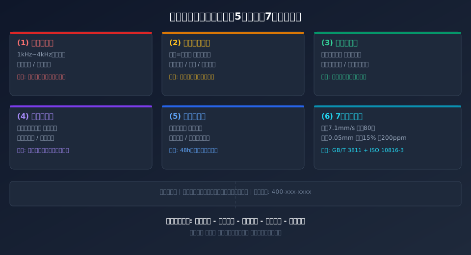
Crane Reducer Abnormal Noise: 5 Fault Signatures & Parameter Comparison
| Abnormal noise Type | Sound Characteristics and Frequency Range | Primary Fault Causes and Response Time Limits |
|---|---|---|
| High-Frequency Whistle | 1kHz~4kHz Piercing Shrill, Accompanied by Rotational speed Rise | Lubrication Poor Condition/Oil Film Rupture, Immediate Shutdown and Inspection |
| Periodic Clicking Sound | Rhythmic Impact, Frequency Equal to Shaft Rotational Frequency or Bearing Fault Frequency | Tooth Surface Pitting/Tooth Breakage/Bearing Spalling, Immediate Shutdown |
| Dull Rumbling Sound | Low-Frequency Continuous Rumble, Accompanied by Gearbox Vibration | Excessive Meshing Clearance/Severe Tooth Surface Wear, Planned Shutdown |
| Intermittent Creaking Sound | Irregular Sharp Friction, Metal-to-Metal Scraping | Cage Damage/Foreign Object, Immediate Shutdown and Inspection |
| Continuous Rustling Sound | Fine Abrasive Grinding Sound, Low Volume but Continuous | Oil Contamination/Micro-motion Wear,48hSchedule Maintenance Within |
| Low-Frequency Structural Vibration | 10~50HzLow-Frequency, Non-Gear Shaft Bearing Characteristics | Gearbox Resonance/Loose Foundation Bolts, Planned Maintenance Air Compressor |
Crane Reducer Vibration Maintenance Standards: 7 Key Indicators vs. ISO 4301 Acceptance Criteria
| Detection Item | Standard Limits and Detection Method | Exceedance Handling Measures and Reference Standard |
|---|---|---|
| Accompanied by Gearbox Vibration Start Button(RMS) | Not Exceeding7.1mm/s(New Machine Not Exceeding4.5mm/s), Acceleration Sensor Radial/Axial | If Exceeded, Perform Spectrum Analysis Positioning Post-Fault Overhaul, Exceedance Handling Measures and Reference ISO 10816-3 |
| Bearing Temperature Rise | Not Exceeding Ambient Temperature+40°C, Maximum Not Exceeding80°C, Infrared Thermometer Gun/Thermal Imaging | If Overheating, Inspect Lubrication Then Replace Bearing, Exceedance Handling Measures and Reference ISO 4301 Crane Design Standard-2008 |
| Gear Backlash | Module3~6mm:0.10~0.20mm, Module6~10mm:0.15~0.30mm, Feeler Gauge/Lead Wire Method | If Out of Tolerance, Air Compressor Center Distance or Replace Gear Pair, Exceedance Handling Measures and Reference ISO 4301 Crane Design Standard |
| Couplingshaft alignment Deviation | Radial Not Exceeding0.05mm, Angle Not Exceeding0.05mm/100mm, Laser Alignment Gauge/dial indicator | If Out of Tolerance, Add or Remove Shimsbow shackle Tighten Jacking Screws Air Compressor Re-Measure to Confirm After, Exceedance Handling Measures and Reference Kelude Heavy Industry Standard |
| Lubricating Oil Viscosity Change | 40Kinematic Viscosity at °CLowering Not Exceeding15%, Portable Viscometer Detection | If Exceeded, Immediately Change Oil and Inspect Sealing, Exceedance Handling Measures and Reference FEM 1.001 |
| Anchor Bolt Torque | M16:210~250Nm, M20:410~490Nm, Torque Check Individually with Wrench | Below70%Loosen All and Re-Tighten Diagonally in Two Passes, Mark with Paint Line |
| Contact pattern Ratio | Tooth Height Not Less Than45%, Tooth Length Not Less Than60%, Red Lead Paste Contact Check Under Load Detection | If Not Compliant, Lap-Run In or Replace as a Pair Gear Pair, Exceedance Handling Measures and Reference ISO 4301 Crane Design Standard |
Crane Reducer Abnormal Noise: Key Maintenance Data & Indicators
Vibration Velocity Limit
≤ 7.1
mm/s RMS
Max Bearing Temperature
≤ 80°C
Per ISO 4301
Coupling Shaft Alignment
≤ 0.05
mm (Radial)
Oil Change Interval
2,000 hrs
or 6 months, whichever comes first
Oil Iron Content Limit
≤ 200
ppm
Gear Contact Pattern
≥ 60%
Along tooth length (ISO 4301)
Related Reading: ISO 4301 Crane Classification: Selecting Between 8 Work Duty Levels and Matching 4 Load Spectra | Crane Rail & Wheel Track Installation Tolerances: 5 Key Indicators and a 3-Step Inspection & Acceptance Method
7 Common Crane Reducer Noise Issues: Troubleshooting & Fixes
Q: What's the difference between a periodic clicking sound and a continuous hum in a crane reducer?
A: A periodic clicking sound that correlates with shaft rotational speed is a classic sign of a broken gear tooth or bearing spalling and requires immediate shutdown. A continuous hum is normal gear meshing noise and is acceptable as long as it stays below 85 dB(A). To confirm, use a strobe light to observe the gear: if you hear a click and see the gear impact once per revolution, the fault is confirmed. Kelude recommends shutting down for inspection within 4 hours of detecting a clicking sound to prevent broken tooth fragments from damaging other gears and bearings.
Q: What specific vibration and noise limits does ISO 4301 set for crane reducers?
A: Under ISO 4301 (formerly ISO 4301, Section 5.8.4), the reducer noise level measured 1 meter from the gearbox housing must not exceed 85 dB(A) at rated speed and rated load. Vibration velocity limits follow ISO 10816-3: for rigidly mounted reducers with 15–300 kW power, a vibration velocity of 7.1 mm/s (RMS) or less is acceptable, while 4.5 mm/s (RMS) or less indicates excellent condition. The standard also requires a gear contact pattern of at least 45% along tooth height and 60% along tooth length, with bearing temperature rise not exceeding ambient temperature +40°C and an absolute maximum of 80°C.
Q: Can I keep using crane reducer oil that has turned milky white from emulsification?
A: No. Milky white oil indicates water content has exceeded 500 ppm, which severely degrades the oil film strength (potentially dropping to below 30% of its normal value). Continuing to run under these conditions will cause micropitting and severe gear wear within 30–50 hours. Corrective action: shut down immediately, drain the emulsified oil completely, flush the gearbox twice with new oil of the same grade, inspect all seals and breather plugs for damage, refill to the proper level, run for 30 minutes, then take another oil sample to confirm water content is below 500 ppm before returning to service.
Q: How much does it cost to replace a gear assembly in a crane reducer?
A: The cost of replacing a reducer gear assembly varies significantly by model and capacity. For a Kelude CD1-5t reducer, the primary gear set (pinion, bull gear, and bearings) typically costs around $270–$370 including labor. A 10t model runs approximately $520–$740, and a 20t model is roughly $890–$1,330. Imported equivalent parts typically cost 2–3 times more than domestic options. We recommend replacing gears in matched pairs and replacing bearings and oil seals at the same time to avoid contact pattern issues from mixing new and worn components.
