Overhead Crane Electrical Troubleshooting: VFD Alarms & PLC Faults
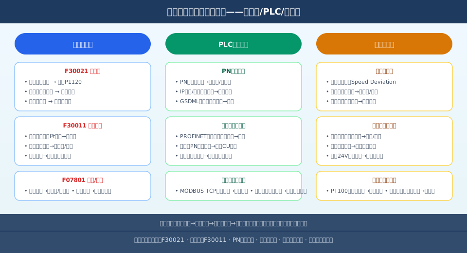
Crane Electrical Fault Troubleshooting is categorized into three main types: VFD faults, PLC communication faults, and sensor failures. VFD faults account for over 50% of all electrical faults, PLC communication faults for 30%, and sensor failures for 20%. A standardized troubleshooting sequence—checking the power supply first, then communication, then sensors, and finally parameter configuration—can reduce unplanned downtime by more than 80%.
Crane electrical fault troubleshooting is handled by type: VFD faults, PLC communication faults, and sensor failures. The diagram below shows a standardized troubleshooting flowchart covering the symptoms, root causes, and corrective steps for common faults. Typical crane electrical faults include: VFD overcurrent F30021 (acceleration too fast or brake not released), VFD motor overload F30011 (load exceeding limits or braking resistor overheating), PROFINET communication loss (cable issue or IP conflict), encoder disconnection (Speed Deviation alarm), and limit switch signal loss (oxidized contacts or misaligned cam). Each fault type has a defined troubleshooting sequence and repair procedure.
VFD Fault Diagnosis and Repair
VFD faults are the most common issue in crane electrical systems, accounting for more than 50% of all electrical failures. Kelude overhead cranes widely use Siemens G120 and ABB ACS880 drives, whose fault code systems and troubleshooting methods are largely consistent. The first step in VFD troubleshooting is to read the fault code displayed on the drive panel or HMI, then cross-reference the fault code table to identify the root cause and implement the fix.
Overcurrent Fault (F30021/G120, 2330/ACS880)
Overcurrent is the most frequent VFD fault on overhead cranes. Troubleshooting steps: Step 1—check whether the acceleration time setting (P1120) is too short. For hoisting mechanisms, the recommended acceleration time is 2–4 seconds; a shorter setting causes current surges that exceed the drive's limit. Step 2—verify that motor parameter identification has been completed (set P1910 to 1 for static identification, or 3 for dynamic identification), and that the motor rated current entered matches the nameplate value. Step 3—check the brake application/release timing: the brake must open only after the VFD has established output torque (with an opening delay of 0.2–0.5 seconds). If the drive outputs power while the brake is still engaged, instantaneous overcurrent will occur. Step 4—measure the motor's insulation resistance to ground (≥1 MΩ using a 500V megohmmeter); insulation degradation can trigger overcurrent trips. Per the insulation requirements of IEC 60204-32, the motor must be taken out of service immediately if insulation resistance to ground falls below 1 MΩ.
In this regard, Kelude's lead technical engineer notes: "When troubleshooting VFD overcurrent faults on cranes, focus on three key elements—acceleration time, brake timing, and motor insulation. Our data shows that over 60% of overcurrent alarms stem from improper brake timing rather than drive hardware issues, so we recommend checking brake open/close sequencing first."
Following the sequence above resolves over 90% of overcurrent faults. If the issue persists, inspect the motor junction box for water ingress or short circuits, and check for abnormal contactor switching on the VFD output side.
Motor Overload Fault (F30011/G120, 2310/ACS880)
Motor overload faults—causes and troubleshooting order: Step 1—confirm that the actual load current does not exceed 110% of the VFD's rated output current (measure three-phase current at the drive output using a clamp meter). Step 2—inspect the braking resistor. An overheated braking resistor causes the drive to derate or trigger an overload alarm; if the resistor surface temperature exceeds 200°C, shut down and allow it to cool. Step 3—evaluate whether hoist duty cycles exceed the design specification. Frequent start/stop operation (more than 60 cycles per hour) prevents adequate motor cooling and can trigger overload protection.
If all checks above are normal, verify the electronic thermal overload relay parameters (P305 series)—the current threshold may be set too low, or the thermal time class may be inappropriate (Class 10 is recommended for crane duty with frequent start/braking).
PLC Communication Fault Troubleshooting
PLC communication faults account for roughly 30% of electrical faults, primarily presenting as PROFINET communication loss, VFD communication timeouts, and host computer connection failures. Troubleshooting follows a bottom-up approach from the physical layer to the application layer.
PROFINET Communication Loss
Troubleshooting steps: Step 1—observe the port LEDs on the network switch and each PN device. A steady green LED indicates normal operation, yellow flashing indicates data exchange, while off or red indicates a communication fault. Step 2—check the physical network cable connections. Industrial shielded cables must be CAT5e or higher; verify RJ45 connectors are secure and cables show no signs of damage. Step 3—verify IP addresses and device names. All PN devices must be on the same subnet (e.g., 192.168.0.x/24), and device names must match those configured in the TIA Portal project—note that names are case-sensitive.
Step 4—check that the GSDML file version matches the VFD firmware version. GSDML files for G120 drives are available on the Siemens website and must be imported into TIA Portal, followed by a recompile of the hardware configuration. Kelude's lead engineer emphasizes: "In PROFINET troubleshooting, many field engineers immediately suspect hardware failure, but in reality 80% of communication issues are at the physical layer—either loose cable connectors or incorrect IP configuration. Start at the switch port LEDs and work your way up." Step 5—check bus load. When more than 8 stations are connected to a single switch or data volumes are high, consider cascading switches or segmenting the network.
VFD Communication Timeout
When the PLC reports a VFD communication timeout, follow this sequence: Step 1—verify the PROFINET cycle time setting is appropriate (for overhead crane systems, RT mode with a cycle time of 4–8 ms is recommended; excessively short cycle times cause timeouts due to interference). Step 2—check whether the VFD control unit (CU) has failed. If the PN LED is abnormal, try reseating the CU or restoring factory defaults and reconfiguring. Step 3—connect a laptop directly to the VFD's PN port to test communication and rule out a faulty switch port.
Sensor Failure Troubleshooting
Sensor failures account for approximately 20% of electrical faults, primarily presenting as encoder signal loss, limit switch failure, and temperature sensor measurement deviation. The focus of sensor troubleshooting is on signal cabling and the mechanical condition of the sensor itself.
Encoder Faults
An encoder fault on the hoist typically triggers a VFD speed deviation alarm (the difference between the setpoint and actual speed exceeds the monitoring threshold). Troubleshooting steps: Step 1: Visually inspect the encoder coupling for looseness — a loose mechanical connection between the encoder and motor shaft causes feedback deviation. Re-secure the coupling and verify shaft alignment with an alignment tool. Step 2: Check the encoder cable for damage. Encoder cables are high-flex cables that tend to break inside the cable carrier after prolonged trolley travel. Use a multimeter to test continuity on each conductor. Step 3: Check the encoder power supply (typically DC 5V or DC 24V). A supply voltage deviation exceeding ±5% will cause erratic encoder pulses.
Limit Switch Faults
A limit switch fault appears as the equipment continuing to run after the switch has been tripped (safety circuit failure), or a limit fault being reported when the switch has not been tripped. Troubleshooting steps: Step 1: Use a multimeter to test the normally closed (NC) contact of the limit switch — the contact should be closed when the switch is in its untripped state. Contacts exposed to dusty environments for extended periods tend to oxidize, causing poor contact. Step 2: Check whether the mechanical cam (trip dog) has shifted. On the Hoisting Height Limit Switch, the cam position drifts gradually as the wire rope stretches, requiring readjustment once per quarter. Per TSG Q7015-2016 Rules for Periodic Inspection of Lifting Appliances, the Hoisting Height Limit Switch is classified as a Category A safety device and must undergo a functional test quarterly, with results recorded. Step 3: Verify that the DI module channel receiving the limit switch signal is functioning properly — the LED indicator light on the PLC DI point can serve as a reference.
Analog Sensor Faults
Faults in analog sensors such as temperature sensors and current transmitters typically appear as abnormal PLC readings (out of range or stuck at a constant value). Troubleshooting steps: Step 1: Confirm the sensor supply voltage (24V DC) is present and measure the voltage at the transmitter terminals. Step 2: Disconnect the sensor wiring and use a signal generator to simulate the standard signal (4–20 mA or PT100 resistance) to test whether the PLC AI module channel is functioning. Step 3: Verify that the transmitter measuring range matches the PLC program configuration.
Troubleshooting Tools and Fault Records
Electrical troubleshooting on an overhead crane requires a basic toolset: a multimeter (for voltage, resistance, and continuity measurements), a clamp meter (for measuring motor three-phase current), a megohmmeter / insulation tester (500V/1000V for insulation resistance testing), a signal generator (for simulating 4–20 mA or PT100 signals to test AI channels), and a laptop with TIA Portal installed for direct PLC program access and debugging.
Every troubleshooting session should record the following: time of fault occurrence, fault code and observed symptoms, equipment operating status at the time (load, speed, operating mode), the step-by-step troubleshooting process with results at each stage, and the root cause and corrective action taken. Fault records form the foundation of preventive maintenance. Kelude recommends using a standardized fault record table, analyzing the distribution of fault causes quarterly, and developing preventive maintenance plans targeting high-frequency fault types. For routine electrical system maintenance requirements and safety device inspection intervals, refer to the control circuit and safety circuit sections of the 5-Step Crane Electrical System Design approach.
Crane Electrical Fault Code Quick Reference
| Fault Type | G120Code | ACS880Code | Most Likely Cause | Troubleshooting Priority |
|---|---|---|---|---|
| Over Current | F30021 | 2330 | Acceleration Too Fast or Brake application Not Enabled | ①acceleration time ②Brake application Interlock |
| Motoroverload | F30011 | 2310 | Load Overlimit or Braking Resistor Overheating | ①Measured Current ②Braking Resistor |
| Motor Stall / Locked Rotor | F30003 | 7121 | Mechanism Jammed or Brake Not Released | ①Mechanism Lubrication ②Brake application Status |
| Start Button Deviation | F7900 | 7381 | Encoder Feedback Abnormal or Stall | ①Encoder Coupling ②Cable |
| Phase Loss | F07801 | 3130 | Power Supply Phase Loss or Fuse Blown / Fusing | ①Power Supply ②Fuse ③Terminal |
| DCOvervoltage | F30002 | 3210 | Braking Energy Feedback Excessive | ①deceleration time ②Braking Resistor |
| Grounding Fault | F30015 | 2320 | Motor Acceleration Too Fast or Cable Insulation Damage | ①Megohmmeter (Insulation Tester)Insulation Test |
VFD Fault Distribution
Overcurrent accounts for 40% of crane VFD faults (acceleration too fast / brake not released), motor overload 25% (load / braking resistor), communication timeout 15% (PN interruption), phase loss 10%, and other causes 10%.
Communication Troubleshooting Tools
Essential tools: network cable tester (RJ45 continuity / wire mapping), laptop with TIA Portal (online diagnostics / I/O status readout), network switch port LEDs (green = normal, red = fault), and PST tool (assign PN device IP address and name).
Encoder Failure Causes
Three primary causes of encoder failure: loose coupling accounts for 60% (vibration loosens mounting bolts), cable wear 25% (drag chain bend radius too small), and encoder element failure 15% (bearing wear / electronic component aging).
Limit Switch Failure Causes
Limit switch faults: contact oxidation / poor contact 50%, trip block misalignment 30% (wire rope stretch / vibration displacement), mechanical jamming 15%, and water ingress short circuit 5%. Adjustment and maintenance are required quarterly.
Troubleshooting Sequence
For any fault category, follow this order: check Power Supply first (supply voltage / fuse / switching power supply), then communication (LEDs / cable / IP / device name), then sensors (encoder / limit switch / transmitter), and finally parameters (acceleration time / tuning / protection thresholds).
Fault Record Template
Record for each troubleshooting session: date/time + equipment ID + fault code + symptom + operating status + step-by-step diagnostic results + root cause + repair method + time spent. Perform a statistical analysis of high-frequency faults quarterly and develop a Preventive Maintenance plan.
Crane VFD Fault Diagnosis FAQ
Q: What should I do when the crane VFD trips on overcurrent?
A: For an overcurrent fault on the crane VFD (G120 F30021 / ACS880 2330), troubleshoot in the following order: ① Check whether acceleration time P1120 is too short (2–4 seconds recommended for hoisting) ② Verify that motor auto-tuning has been completed ③ Check the brake application interlock timing (brake release delay 0.2–0.5 seconds) ④ Measure motor insulation resistance (≥1MΩ). Following this sequence resolves over 90% of overcurrent faults. If the issue persists, inspect the motor wiring junction box for water ingress or short circuits.
Q: What causes communication loss between the crane PLC and VFD?
A: Common causes of PROFINET communication interruption: ① Loose cable or RJ45 connector (check PN port LEDs) ② Incorrect IP address or device name configuration (must match the TIA Portal project) ③ GSDML file version incompatible with the VFD firmware ④ Faulty network switch port (test by switching ports) ⑤ CU control unit failure on the VFD (reinstall CU or restore factory settings). Troubleshoot layer by layer, from the physical layer up to the application layer.
Q: How do I diagnose a hoisting encoder fault?
A: A hoisting encoder fault typically triggers a speed deviation alarm on the VFD (G120 F7900 / ACS880 7381). Diagnostic steps: ① Visually inspect the encoder coupling for looseness (vibration-related bolt loosening accounts for 60% of faults) ② Use a multimeter to check continuity on each core of the encoder cable (cable wear accounts for 25%) ③ Verify encoder power supply voltage stability (DC5V or DC24V, deviation ≤±5%) ④ Use an oscilloscope to observe the A/B phase signals and confirm pulse integrity.
Q: How can overhead crane electrical faults be prevented?
A: The key to preventing electrical faults in overhead cranes is establishing a standardized inspection and maintenance schedule. This includes weekly checks for loose terminals inside the control cabinet and cooling fan operation, monthly cleaning of dust buildup inside the control cabinet, quarterly inspections of the encoder coupling and limit switch bumper positions, and an annual full-system insulation test (≥1MΩ/500V). Keep a fault log and perform quarterly statistical analysis of recurring fault types to develop targeted preventive actions. For routine maintenance intervals on the electrical system, refer to the electrical system section of the overhead crane maintenance manual.