

Electrical Controls for Overhead Cranes: From System Architecture to Troubleshooting—A Comprehensive Guide to Variable-Frequency PLC Anti-Sway Control
📌 Full Line of Overhead Crane Electrical Control Systems It covers five major topics: electrical system architecture design, variable frequency drive parameter settings, PLC and PROFINET networking, electronic anti-sway control, and electrical troubleshooting. The five-part series is organized according to the design process: system architecture → VFD parameters → PLC networking → anti-sway control → troubleshooting, forming a comprehensive knowledge system that spans from design to maintenance.
This series on overhead crane electrical control systems consists of five articles, arranged according to the design process: System Architecture → Variable Frequency Parameters → PLC Networking → Anti-Sway Control → Troubleshooting. The figure below is an overview of this series, showing the distribution of core content across each article. The core standards covered in this series include GB/T 5226.1-2019-2019 "Electrical Safety of Machinery," GB/T 15969.1-2017.2-2008-2008 “Programmable Logic Controllers,” and IEC 61784-1:2019 “Industrial Communication Networks.” The hardware platform primarily consists of Siemens S7-1200/1500 PLCs and G120 variable-frequency drives, covering a full range of application scenarios from single-girder overhead cranes with capacities under 10 metric tons to double-girder overhead cranes with capacities exceeding 16 metric tons. All overhead crane products from Krude Heavy Industry are designed and manufactured in accordance with the technical standards outlined in this series.
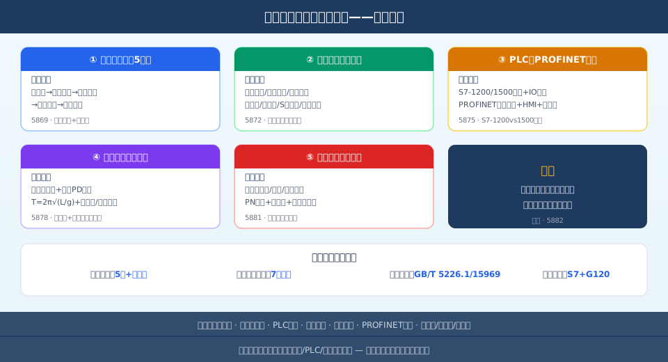
Overview of the Series on Electrical Controls for Overhead Cranes
Series Navigation
This series is organized according to the design process for overhead crane electrical control systems; we recommend reading it in numerical order. Begin by gaining an overall understanding of the system architecture, then delve into specific aspects such as variable frequency drive parameters and PLC networking, and finally reinforce your practical application skills through the troubleshooting section. All overhead crane products from Krude Heavy Industry are manufactured in strict accordance with this design process to ensure that every unit passes comprehensive electrical safety verification.
① A 5-Step Approach to Designing Overhead Crane Electrical Systems — A comprehensive three-tier architecture spanning the main circuit to the safety circuit. It covers four phases: main circuit wiring, control circuit I/O allocation, three-level protection for the safety circuit, PROFINET networking, and system-wide debugging.
② Overhead Crane Inverter Parameter Setting Table — Configuration of speed curves and control modes for the hoist and trolley. Motor self-tuning, multi-speed/analog speed setpoint, S-curve acceleration and deceleration, brake interlock timing, and protection function parameters.
③ PLC Control for Overhead Cranes: From Selection to Networking — S7-1200 Configuration and PROFINET Communication Solution. PLC Selection (S7-1200 vs. S7-1500), I/O Point Table Design, PROFINET Device Configuration, HMI Interface, and Integration with the Host Computer.
④ Manual for Controlling the Swing of Loads on Overhead Cranes — Principles of electronic anti-sway systems and parameter tuning methods. Input shaping methods using ZV/ZVD shapers, closed-loop PD control, calculation of the sway period T = 2π√(L/g), and encoder/vision sensor solutions.
⑤ Hands-On Troubleshooting of Overhead Crane Electrical Faults — Complete log of inverter alarms, PLC interrupts, and sensor failures. Troubleshooting for overcurrent (F30021) and motor overload (F30011) faults, PROFINET communication diagnostics, and handling of encoder cable breaks and limit switch failures.
💬 Comments from the Technical Director at Krude Heavy Industries:
“Safety must be the top priority in the design of overhead crane electrical control systems. In actual projects, Krude Heavy Industry strictly adheres to the three-level protection architecture for safety circuits specified in the GB/T 5226.1-2019 standard, while achieving efficient coordinated control between the PLC and the variable frequency drive through PROFINET communication. From 10-metric-ton single-girder to 50-metric-ton double-girder overhead cranes, this comprehensive technical system has been validated through years of practical application and is currently the most mature and reliable solution.”
— Technical Director of Electrical Systems at Krude Heavy Industries
Related Recommendations
The electrical control system of overhead cranes is closely related to variable-frequency speed control and anti-sway control. The following articles can serve as supplementary reading for this series:
Design and Installation of Electrical Schematics for Overhead Cranes: A Comprehensive Analysis of Main Circuits, Control Circuits, and Safety Circuits — An in-depth analysis of the electrical system from a schematic perspective, covering AC 380 V main circuit wiring, DC 24 V control circuit signals, and hard-wired protection for safety circuits.
Crane Maintenance Manual: Standard Intervals for Everything from Routine Lubrication to Replacement of Key Components — The electrical system is one of the six major maintenance components and includes standard electrical maintenance procedures such as control cabinet purging, terminal tightening, and insulation testing.
Frequently Asked Questions (FAQ)
Q: What is the design sequence for an overhead crane's electrical control system?
Answer: It is recommended to design the electrical control system for an overhead crane using a 5-step approach: Step 1: Main Circuit Design (Power Supply Inlet → Circuit Breaker → Reactor → Variable Frequency Drive → Motor); Step 2: Control Circuit Design (PLC → I/O → Relays → Peripheral Signals), Step 3: Safety circuit design (emergency stop → limit switches → safety relays → dual-brake redundancy), Step 4: Communication network design (PROFINET → HMI → host computer), Step 5: System commissioning (power-on check → no-load operation → load operation → safety verification).
Q: How do you set the parameters for the variable frequency drive in an overhead crane's electrical system?
Answer: Setting the parameters for an overhead crane frequency converter involves three steps: ① Motor parameter autotuning (performed after entering nameplate parameters, either static or dynamic tuning) ② Speed curve setup (4–8 speed segments or analog input; acceleration/deceleration times for hoisting: 2–4 s / 4–6 s; S-curve transition: 0.2–0.5 s) ③ Braking and protection parameters (brake interlock timing, DC injection braking + braking resistor, Class 10 overload protection). The standard configuration for a 10-metric-ton overhead crane hoisting drive is 11 kW; for the main girder, 2 × 3 kW; and for the trolley, 1.5 kW.
Q: What are the common malfunctions in overhead crane electrical systems?
Answer: The percentage breakdown of common faults in overhead crane electrical systems is as follows: inverter overcurrent (F30021) accounts for 40%; motor overload (F30011) accounts for 25%; PROFINET communication interruption accounts for 15%, encoder wire break (F7900) accounts for 10%, and others (phase loss/ground fault/overvoltage) account for 10%. The troubleshooting sequence is as follows: first check the power supply, then check communication, then check sensors, and finally check parameter settings. It is recommended to maintain a fault log, perform quarterly statistical analysis, and develop preventive measures.
Q: How is the anti-sway control for overhead cranes implemented?
Answer: There are two methods for controlling crane sway: the input shaping method and the closed-loop control method. The input shaping method does not require sensors; it decomposes the acceleration command into a pulse sequence at intervals of T/2 (half the sway period) so that the sway components cancel each other out, resulting in residual sway of ±30–80 mm. The closed-loop control method uses an encoder or vision sensor to detect the sway angle in real time and corrects the speed setpoint via a PD controller, resulting in residual sway of ±15–30 mm. The input shaping method is recommended for overhead cranes with a capacity of less than 10 metric tons, while the closed-loop control method is recommended for high-precision applications.
Q: What is the design sequence for an overhead crane's electrical control system?
Answer: It is recommended to design the electrical control system for an overhead crane using a 5-step approach: Step 1: Main Circuit Design (Power Supply Inlet → Circuit Breaker → Reactor → Variable Frequency Drive → Motor); Step 2: Control Circuit Design (PLC → I/O → Relays → Peripheral Signals), Step 3: Safety circuit design (emergency stop → limit switches → safety relays → dual-brake redundancy), Step 4: Communication network design (PROFINET → HMI → host computer), Step 5: System commissioning (power-on check → no-load operation → load operation → safety verification).
Q: How do you set the parameters for the variable frequency drive in an overhead crane's electrical system?
Answer: Setting the parameters for an overhead crane frequency converter involves three steps: ① Motor parameter autotuning (performed after entering nameplate parameters, either static or dynamic tuning) ② Speed curve setup (4–8 speed segments or analog input; acceleration/deceleration times for hoisting: 2–4 s / 4–6 s; S-curve transition: 0.2–0.5 s) ③ Braking and protection parameters (brake interlock timing, DC injection braking + braking resistor, Class 10 overload protection). The standard configuration for a 10-metric-ton overhead crane hoisting drive is 11 kW; for the main girder, 2 × 3 kW; and for the trolley, 1.5 kW.
Q: What are the common malfunctions in overhead crane electrical systems?
Answer: The percentage breakdown of common faults in overhead crane electrical systems is as follows: inverter overcurrent (F30021) accounts for 40%; motor overload (F30011) accounts for 25%; PROFINET communication interruption accounts for 15%, encoder wire break (F7900) accounts for 10%, and others (phase loss/ground fault/overvoltage) account for 10%. The troubleshooting sequence is as follows: first check the power supply, then check communication, then check sensors, and finally check parameter settings. It is recommended to maintain a fault log, perform quarterly statistical analysis, and develop preventive measures.
Q: How is the anti-sway control for overhead cranes implemented?
Answer: There are two methods for controlling crane sway: the input shaping method and the closed-loop control method. The input shaping method does not require sensors; it decomposes the acceleration command into a pulse sequence at intervals of T/2 (half the sway period) so that the sway components cancel each other out, resulting in residual sway of ±30–80 mm. The closed-loop control method uses an encoder or vision sensor to detect the sway angle in real time and corrects the speed setpoint via a PD controller, resulting in residual sway of ±15–30 mm. The input shaping method is recommended for overhead cranes with a capacity of less than 10 metric tons, while the closed-loop control method is recommended for high-precision applications.
