

A 5-Step Approach to Overhead Crane Electrical System Design: A Complete Three-Tier Architecture from the Main Circuit to the Safety Circuit
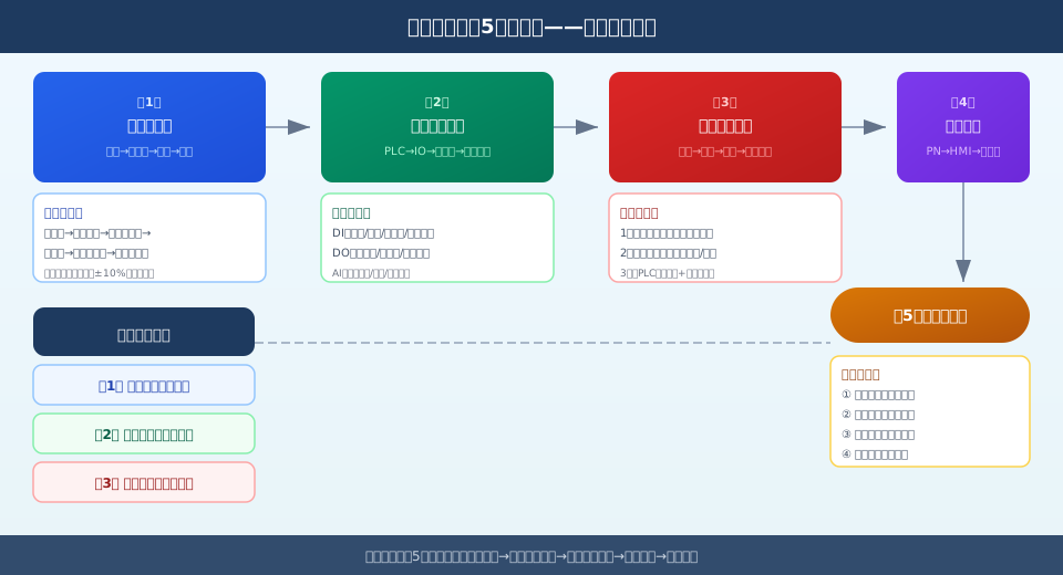
The 5-Step Design Method for Overhead Crane Electrical Systems covers the entire electrical system design process, from the main circuit to final system commissioning. The figure below illustrates the topological relationships among the three-layer architecture: the main circuit (power layer), the control circuit (logic layer), and the safety circuit (protection layer). The design of crane electrical systems must comply with GB/T 5226.1-2019-2019 “Electrical Safety of Machinery” and GB/T 3811-2008-2008 “Design Code for Cranes.” Core design principles: Power circuit wiring is isolated from control signal lines to prevent electromagnetic interference; safety circuits use series-connected normally closed contacts to ensure fail-safe operation; and the communication network employs PROFINET industrial Ethernet to enable real-time data exchange.
📌 Design of the Crane Electrical System Implement using a 5-step approach: Main Circuit Design → Control Circuit Design → Safety Circuit Design → Communication Network Design → System Commissioning. A complete overhead crane electrical system is divided into three layers: the main circuit (power layer) supplies power to the variable-frequency drive and motor; the control circuit (logic layer) executes PLC instructions and acquires peripheral signals; and the safety circuit (protection layer) provides multi-level safety protection, including emergency stop, limit switches, and interlocks. A standardized design process can reduce electrical failures by more than 80%.
The 5-Step Design Method for Overhead Crane Electrical Systems covers the entire electrical system design process, from the main circuit to final system commissioning. The figure below illustrates the topological relationships among the three-layer architecture: the main circuit (power layer), the control circuit (logic layer), and the safety circuit (protection layer). The design of crane electrical systems must comply with GB/T 5226.1-2019-2019 “Electrical Safety of Machinery” and GB/T 3811-2008-2008 “Design Code for Cranes.” Core design principles: Power circuit wiring is isolated from control signal lines to prevent electromagnetic interference; safety circuits use series-connected normally closed contacts to ensure fail-safe operation; and the communication network employs PROFINET industrial Ethernet to enable real-time data exchange.
Step 1: Main Circuit Design
The main circuit is the complete power transmission path from the utility power source to the motor windings, and it forms the backbone of the overhead crane’s electrical system. The design process proceeds step by step from the power input end toward the load end.
1.1 Power Supply Inlet and Main Circuit Breaker
A three-phase, five-wire (TN-S system) 380V/50Hz power supply is fed in from the plant’s distribution panel. The main feeder uses a molded-case circuit breaker (MCCB), with a rating selected to be 1.25 to 1.5 times the rated current of the entire unit. For a 10-metric-ton overhead crane, the recommended rated current for the main circuit breaker is 160–250 A. The cross-sectional area of the feeder cable is calculated based on the current-carrying capacity; a copper-core cable with a cross-sectional area of 3×70 + 2×35 mm² is recommended.
1.2 Line Reactor and Frequency Converter
Install a three-phase input reactor (inductance: 2–41 TP3T) downstream of the main circuit breaker to suppress interference from harmonics and voltage spikes affecting the variable frequency drives. For the hoisting mechanism, select SIEMENS G120 series or ABB ACS880 series variable frequency drives (VFDs), with power ratings selected at 1.1–1.3 times the motor’s rated power. The power ratings of the main and auxiliary travel VFDs should be 1/3 to 1/2 of the hoisting power. 10-metric-ton overhead crane inverter configuration: Hoisting 11 kW, main girder 2 × 3 kW, trolley 1.5 kW.
1.3 Output Circuit and Motor Wiring
Install an output reactor (inductance: 1–21 TP3T) on the output side of the variable frequency drive to protect the motor windings from dV/dt surges. For the hoisting motor, the YZR series wound-rotor motor is recommended, equipped with a brake and an encoder on the output shaft. Shielded cables must be used for motor wiring, with the shield grounded at one end. Select the braking resistor value according to the inverter manual, and install it on the top or side of the cabinet in a well-ventilated area.
Once the main circuit design is complete, the following must be verified: the cable current-carrying capacity is ≥1.25 times the rated current; the circuit breaker’s breaking capacity is ≥the expected short-circuit current; and the cable length from the variable frequency drive to the motor does not exceed the drive’s allowable limit (≤50 m without an output reactor; ≤150 m with an output reactor). All overhead crane products from Krude Heavy Industry are designed with main circuits and cables selected in accordance with the above standards.
Step 2: Control Loop Design
The control loop is the logical core of an electrical system; it is responsible for acquiring operating signals and sensor data, and for driving contactors and variable-frequency drives to execute actions. The control loop radiates outward from the PLC to various I/O stations and actuators.
2.1 PLC Selection and I/O Allocation
For medium- to large-sized overhead cranes, we recommend using the Siemens S7-1200 (for small- to medium-sized applications) or the S7-1500 (for large-scale or high-performance applications). Estimated PLC I/O points: Approximately 24–40 DI (digital input) points, including pushbutton signals, limit switch signals, encoder signals, and safety relay feedback signals. Approximately 16–24 DO (digital output) points, including contactor coils, indicator lights, and buzzers. AI (Analog Inputs): Approximately 4–8 points, including inverter current feedback and temperature sensors.
The signal acquisition terminal blocks are arranged in sections separated by partitions. The 24V DC power supply is divided into groups, with no more than 8 loads per group. DI signals uniformly use a 24V PNP configuration (source-type input), while DO signals use an NPN configuration (sink-type output) to drive intermediate relays.
2.2 Variable Frequency Drive Control Modes
The variable frequency drive (VFD) and PLC communicate via the PROFINET fieldbus, transmitting speed setpoints, status feedback, and error codes in real time. The hoisting VFD employs encoder-based vector control (closed-loop), with a speed accuracy of ≤0.01%; The hoist, main girder, and trolley inverters use encoderless vector control (open-loop), with a speed accuracy of ≤0.51 TP3T. The inverters receive 16-bit speed setpoint words from the PLC (0–16384 corresponding to 0–rated frequency) and simultaneously feed back actual speed, current values, and fault codes to the PLC.
The relay control boards are centrally located; all intermediate relays are powered by 24 V DC, with contact ratings of 250 V AC/5 A. Contactors must be rated for at least 1.5 times the rated current, and the main contactor and braking contactor must be electrically interlocked.
Step 3: Safety Circuit Design
The safety circuit is the most critical level in an electrical system; it uses a series-connected normally closed contact configuration to ensure that the entire machine stops immediately if any link in the circuit is broken. The safety circuit operates independently of the PLC control logic and provides rapid disconnection through a hardware circuit.
3.1 Three-Tier Security Protection Architecture
Level 1: Emergency Stop Button Series Circuit. One emergency stop button (red mushroom-head, self-latching type) is installed at the operator’s console and one at each end of the main girder. Pressing a button instantly cuts off power to the main contactor, causing all variable-frequency drives and motors to lose power and stop. Level 2: Limit Switch Safety Circuit. The normally closed contacts of the hoist height limit switches (upper limit + lower limit), the gantry travel limit switches, and the trolley travel limit switches are connected in series to the safety circuit. When any limit switch is triggered, the enable signal to the corresponding mechanism’s variable frequency drive is cut off. Level 3: Safety Relay and Dual-Brake Redundancy. The hoisting mechanism employs a dual-brake configuration (service brake + safety brake). A safety relay monitors the operational status of both brakes; if one fails, the other can still apply the brakes.
The technical director at Krude Heavy Industry noted: ”The three-tier safety protection architecture is the cornerstone of the overhead crane’s electrical system safety. In particular, the hoisting mechanism employs a redundant dual-brake configuration that provides a final safety barrier under extreme operating conditions. This is a proven solution that we have validated through hundreds of overhead crane projects.”
3.2 Safety Interlocks and Interlocking
Hoist and Trolley Interlock: The trolley drive is prohibited from accelerating while the hoist mechanism is in operation. Main Crane and Trolley Wheelbase Interlock: Multiple overhead cranes in the same bay must be interlocked via PLC communication to prevent collisions. Brake and Variable Frequency Drive (VFD) Interlock: The brake release signal must be received only after the VFD output has been established to prevent hook slippage. After an emergency stop, no mechanisms may restart automatically; they must be restarted only after manually resetting the emergency stop button.
Once the safety circuit design is complete, it must be verified using a multimeter: when the emergency stop button is pressed, the enable terminals of all variable frequency drives must be disconnected; when a limit switch is triggered, the corresponding mechanism must stop; and when the brake is open-circuited, the hoisting contactor must not engage. All verification data must be recorded and included in the factory inspection report. Krude Heavy Industry strictly adheres to this verification process in the design of safety circuits to ensure that the safety performance of every overhead crane meets the required standards.
💬 Comment from the Technical Director at Krude Heavy Industries:
“The most easily overlooked aspect in the design of overhead crane electrical systems is the coordination between safety circuits and communication networks. Many on-site malfunctions appear to be caused by inverter error messages, but the root cause often lies in signal interference in the control circuit or aging contacts in the safety circuit. Based on our experience in actual projects, we recommend thoroughly implementing a three-layer isolation architecture during the design phase—maintaining a distance of ≥300 mm between the main circuit power cables and control signal wires, using forced-guidance relays exclusively for safety circuits, using shielded twisted-pair cables for communication with single-ended grounding—these three measures can eliminate post-commissioning issues for systems rated at 80% and above. Additionally, the heat dissipation requirements for braking resistors are often underestimated; we recommend installing forced-air cooling fans at the top of the cabinet and setting the thermal switch to activate at 55°C.”
Step 4: Communication Network Design and Step 5: System-Level Debugging
4.1 Communication Network Architecture
The crane communication network uses PROFINET industrial Ethernet as its backbone, connecting the PLC CPU, distributed I/O stations, variable frequency drives, and HMI touchscreens. The network topology is star-shaped, with all devices connected to a switch. The host computer (shop-floor MES system or PC) communicates with the PLC via Ethernet to collect operational data and fault information. Industrial-grade shielded network cables (CAT5e or higher) are used for communication, and during installation, they must be routed at least 200 mm away from power cables to prevent electromagnetic interference.
4.2 System Commissioning Process
Step 5: System commissioning consists of four phases. Phase 1: Power-on inspection: Measure the main circuit insulation resistance (≥1 MΩ at 500 V using a megohmmeter), verify that the three-phase voltages are balanced (deviation ≤ 21 TP3T), and check that all circuit breakers open and close normally. Stage 2: No-Load Intermittent Operation: Power on each inverter sequentially, set the motor parameters (rated voltage/current/speed/power factor), and perform no-load intermittent operation to verify that the motor rotates in the correct direction and that the inverters are fault-free. Stage 3: Load Commissioning: Apply rated loads of 50%, 100%, and 125% to the hoisting mechanism to verify brake slip (≤v/100) and the inverter’s output current (≤rated current 110%). Stage 4: Safety Function Verification: Test the emergency stop, limit switches, interlocks, and brake redundancy one by one. Issue a commissioning report after all indicators meet the requirements.
The technical director at Krude Heavy Industries pointed out: ”The commissioning of the entire machine must be carried out strictly in four sequential stages; skipping any step could introduce serious safety hazards. We require that complete test data records be maintained throughout the entire commissioning process to ensure that every step is traceable and verifiable.”
Comparison of Key Parameters for Each Component of the Overhead Crane Electrical System
Design Phase Core Components Key Parameters Selection Criteria Common Mistakes Main Circuit MCCB Circuit Breaker · Feeder Reactor · Variable Frequency Drive · Braking Resistor Rated current: 1.25–1.5 times · Reactor: 2–4% GB/T 5226.2-2019.1-2019-2019 The cable is too long and no output reactor has been installed. Control Loop PLC · I/O Modules · Intermediate Relays · Encoders DI24–40·DO16–24·AI4–8·DC24V GB/T 15969.1-2017.2-2008 DI/DO Shared Power Supply Not Grouped or Isolated Safety Circuit Emergency Stop Button · Limit Switch · Safety Relay · Brake Emergency stop response time ≤ 200 ms · Limit switch travel ≥ 200 mm GB/T 28264-2017 The safety circuit relies on the PLC program rather than hardwiring. Communications Networks Switches · PROFINET · HMI · Host Computer CAT5e · Minimum clearance from power lines: ≥200 mm IEC 61784 Running Communication Cables and Power Cables in Parallel System Commissioning Multimeter · Megohmmeter · Clamp Meter · Tachometer Insulation ≥ 1 MΩ; Braking slip ≤ v/100 TSG Q7015-2016 Skip the no-load jog and apply the load directly
Main Circuit Design Specifications
The power supply input uses a TN-S three-phase, five-wire system rated at 380 V/50 Hz. The main circuit breaker should be selected with a rated current of 1.25 to 1.5 times the motor’s rated current, and the input reactor should have an inductance of 2 to 41 TP3T. The inverter should be selected with a power rating of 1.1 to 1.3 times the motor’s power, and the output reactor should have an inductance of 1 to 21 TP3T.
Control Loop Signal Distribution
PLC DI signals 24–40 (limit switches/pushbuttons/encoders), DO signals 16–24 (contactors/indicator lights), and AI signals 4–8 (inverter feedback/temperature). The 24V power supply is divided into groups, with each group having ≤8 loads.
Three-Level Protection for Safety Circuits
Pressing the Level 1 emergency stop button cuts off the power supply within ≤200 ms. The 2g limit switch operates reliably when the distance to the limit is ≥200 mm. The hoisting system features a redundant configuration of two brakes; if one fails, the other can still apply the brakes. The safety circuit is independent of the PLC.
Vector Control of Variable Frequency Drives
The hoisting inverter uses closed-loop vector control with an encoder, with a speed accuracy of ≤0.01%. The main and auxiliary hoists use encoder-less open-loop vector control, with a speed accuracy of ≤0.51 TP3T. The 16-bit speed setpoint word (0–16384 corresponds to 0–rated frequency).
PROFINET Networking and Communication
A star-topology switch connects the PLC, variable frequency drive, and HMI. Industrial shielded CAT5e+ network cables must be spaced at least 200 mm apart from power cables. The host computer collects operational data via Ethernet, with cable lengths of no more than 100 m per segment.
Four Stages of System Commissioning
① Insulation test: ≥1 MΩ; three-phase balance: ≤21 TP3T. ② No-load intermittent operation to verify rotation direction; inverter operates without faults. ③ 501 TP3T/1001 TP3T/1251 TP3T load; deceleration under braking: ≤v/100. ④ Verification of all safety functions + commissioning report.
Frequently Asked Questions (FAQ)
Q: What components make up the electrical system of an overhead crane?
Answer: The overhead crane’s electrical system consists of three parts: the main circuit (power supply input → circuit breaker → reactor → variable frequency drive → motor, which transmits power), the control circuit (PLC → I/O modules → relays → encoder/pushbuttons, which performs logic control) , and the safety circuit (emergency stop → limit switches → safety relays → brakes, providing hard-wired safety protection). These three circuits are physically isolated from one another and designed to function independently.
Q: What are the requirements for selecting a frequency converter for an overhead crane?
Answer: The selection of a frequency converter for an overhead crane is based on the heaviest load condition of the hoisting mechanism, and the power rating should be selected at 1.1 to 1.3 times the motor’s rated power. Vector control (with encoder feedback) is recommended for the hoisting mechanism, while encoder-less vector control can be used for the main and auxiliary trolleys. Typical configuration for a 10-metric-ton overhead crane: hoist 11 kW, main girder 2 × 3 kW, trolley 1.5 kW. Braking resistors and line reactors must be installed.
Q: Why must the overhead crane's safety circuit be independent of the PLC?
Answer: The safety circuit is independent of the PLC for the following reasons: (1) The PLC program may run out of control or crash, causing safety functions to fail; (2) The response time of the hard-wired circuit (≤200 ms) is much faster than the PLC scan cycle (10–50 ms); ③ The safety circuit uses normally closed contacts connected in series; if any contact opens, the power supply is cut off, complying with the fail-safe principle. GB/T 28264-2017 and TSG Q7015-2016 explicitly require that safety circuits be implemented using hard-wired connections.
Q: What should be kept in mind when commissioning the electrical system of an overhead crane?
Answer: Commissioning must be carried out in four stages, one after another; no steps may be skipped. Before powering on, measure the insulation resistance (≥1 MΩ/500 V) and verify that the three-phase voltages are balanced (deviation ≤ 2%). During the no-load phase, power on each inverter individually to verify the motor’s rotation direction. During the load phase, gradually increase the load from 50% to 125%, ensuring that the braking slip does not exceed v/100. Safety function verification must include testing each item individually: emergency stop, limit switches, interlocks, and brake redundancy. All data must be recorded and archived. Krude Heavy Industry recommends that commissioning be performed by a licensed electrical engineer.
| Design Phase | Core Components | Key Parameters | Selection Criteria | Common Mistakes |
|---|---|---|---|---|
| Main Circuit | MCCB Circuit Breaker · Feeder Reactor · Variable Frequency Drive · Braking Resistor | Rated current: 1.25–1.5 times · Reactor: 2–4% | GB/T 5226.2-2019.1-2019-2019 | The cable is too long and no output reactor has been installed. |
| Control Loop | PLC · I/O Modules · Intermediate Relays · Encoders | DI24–40·DO16–24·AI4–8·DC24V | GB/T 15969.1-2017.2-2008 | DI/DO Shared Power Supply Not Grouped or Isolated |
| Safety Circuit | Emergency Stop Button · Limit Switch · Safety Relay · Brake | Emergency stop response time ≤ 200 ms · Limit switch travel ≥ 200 mm | GB/T 28264-2017 | The safety circuit relies on the PLC program rather than hardwiring. |
| Communications Networks | Switches · PROFINET · HMI · Host Computer | CAT5e · Minimum clearance from power lines: ≥200 mm | IEC 61784 | Running Communication Cables and Power Cables in Parallel |
| System Commissioning | Multimeter · Megohmmeter · Clamp Meter · Tachometer | Insulation ≥ 1 MΩ; Braking slip ≤ v/100 | TSG Q7015-2016 | Skip the no-load jog and apply the load directly |
Main Circuit Design Specifications
The power supply input uses a TN-S three-phase, five-wire system rated at 380 V/50 Hz. The main circuit breaker should be selected with a rated current of 1.25 to 1.5 times the motor’s rated current, and the input reactor should have an inductance of 2 to 41 TP3T. The inverter should be selected with a power rating of 1.1 to 1.3 times the motor’s power, and the output reactor should have an inductance of 1 to 21 TP3T.
Control Loop Signal Distribution
PLC DI signals 24–40 (limit switches/pushbuttons/encoders), DO signals 16–24 (contactors/indicator lights), and AI signals 4–8 (inverter feedback/temperature). The 24V power supply is divided into groups, with each group having ≤8 loads.
Three-Level Protection for Safety Circuits
Pressing the Level 1 emergency stop button cuts off the power supply within ≤200 ms. The 2g limit switch operates reliably when the distance to the limit is ≥200 mm. The hoisting system features a redundant configuration of two brakes; if one fails, the other can still apply the brakes. The safety circuit is independent of the PLC.
Vector Control of Variable Frequency Drives
The hoisting inverter uses closed-loop vector control with an encoder, with a speed accuracy of ≤0.01%. The main and auxiliary hoists use encoder-less open-loop vector control, with a speed accuracy of ≤0.51 TP3T. The 16-bit speed setpoint word (0–16384 corresponds to 0–rated frequency).
PROFINET Networking and Communication
A star-topology switch connects the PLC, variable frequency drive, and HMI. Industrial shielded CAT5e+ network cables must be spaced at least 200 mm apart from power cables. The host computer collects operational data via Ethernet, with cable lengths of no more than 100 m per segment.
Four Stages of System Commissioning
① Insulation test: ≥1 MΩ; three-phase balance: ≤21 TP3T. ② No-load intermittent operation to verify rotation direction; inverter operates without faults. ③ 501 TP3T/1001 TP3T/1251 TP3T load; deceleration under braking: ≤v/100. ④ Verification of all safety functions + commissioning report.
Frequently Asked Questions (FAQ)
Q: What components make up the electrical system of an overhead crane?
Answer: The overhead crane’s electrical system consists of three parts: the main circuit (power supply input → circuit breaker → reactor → variable frequency drive → motor, which transmits power), the control circuit (PLC → I/O modules → relays → encoder/pushbuttons, which performs logic control) , and the safety circuit (emergency stop → limit switches → safety relays → brakes, providing hard-wired safety protection). These three circuits are physically isolated from one another and designed to function independently.
Q: What are the requirements for selecting a frequency converter for an overhead crane?
Answer: The selection of a frequency converter for an overhead crane is based on the heaviest load condition of the hoisting mechanism, and the power rating should be selected at 1.1 to 1.3 times the motor’s rated power. Vector control (with encoder feedback) is recommended for the hoisting mechanism, while encoder-less vector control can be used for the main and auxiliary trolleys. Typical configuration for a 10-metric-ton overhead crane: hoist 11 kW, main girder 2 × 3 kW, trolley 1.5 kW. Braking resistors and line reactors must be installed.
Q: Why must the overhead crane's safety circuit be independent of the PLC?
Answer: The safety circuit is independent of the PLC for the following reasons: (1) The PLC program may run out of control or crash, causing safety functions to fail; (2) The response time of the hard-wired circuit (≤200 ms) is much faster than the PLC scan cycle (10–50 ms); ③ The safety circuit uses normally closed contacts connected in series; if any contact opens, the power supply is cut off, complying with the fail-safe principle. GB/T 28264-2017 and TSG Q7015-2016 explicitly require that safety circuits be implemented using hard-wired connections.
Q: What should be kept in mind when commissioning the electrical system of an overhead crane?
Answer: Commissioning must be carried out in four stages, one after another; no steps may be skipped. Before powering on, measure the insulation resistance (≥1 MΩ/500 V) and verify that the three-phase voltages are balanced (deviation ≤ 2%). During the no-load phase, power on each inverter individually to verify the motor’s rotation direction. During the load phase, gradually increase the load from 50% to 125%, ensuring that the braking slip does not exceed v/100. Safety function verification must include testing each item individually: emergency stop, limit switches, interlocks, and brake redundancy. All data must be recorded and archived. Krude Heavy Industry recommends that commissioning be performed by a licensed electrical engineer.
