Overhead Crane PLC Control: S7-1200 Setup & PROFINET Networking

The overhead crane PLC control system is built around a Siemens S7-1200/S7-1500 controller, with PROFINET linking the VFDs and distributed I/O stations. With a typical I/O configuration of DI 24–40 points, DO 16–24 points, and AI 4–8 points, this standardized network architecture can improve communication reliability by over 80% while cutting commissioning time by 30%.

The overhead crane PLC control system serves as the brain of the crane's electrical control system, managing coordinated control, safety interlocks, and fault diagnosis across the hoisting, crane bridge, and trolley mechanisms. Designed to meet the reliability requirements for electrical control systems set forth in GB/T 15969.2-2008 (Programmable Controllers) and ISO 4301 Crane Design Standard, a well-engineered PLC system can reduce electrical fault rates on overhead cranes by more than 60% while significantly improving operational efficiency and safety.

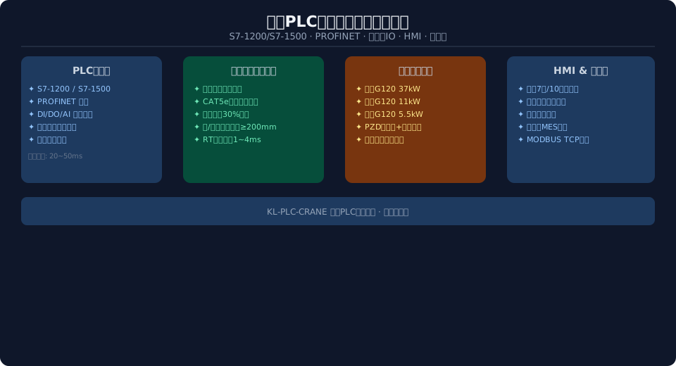
The system uses a Siemens S7-1200/S7-1500 as its core controller, connecting distributed I/O stations and VFDs for each mechanism via PROFINET industrial Ethernet. The PLC acquires signals from operator pushbuttons and sensors, processes them through programmed logic, and outputs control commands to the VFDs and contactors to achieve speed control and direction switching for all three mechanisms. This standardized networking approach simplifies system commissioning and reduces long-term maintenance costs.

Overhead crane PLC control system network topology diagram

Control System Architecture and Core Principles

The overhead crane PLC control system uses a three-tier architecture consisting of the operator layer, control layer, and execution layer. The operator layer includes the master switch, pushbutton station, and HMI touchscreen in the operator cab, handling command input and status display. The control layer, centered on the PLC, communicates with all stations over the PROFINET bus and runs the mechanism interlock logic, safety interlock logic, and fault diagnosis routines. The execution layer comprises the VFDs, brakes, motors, and limit switches for each mechanism, directly carrying out PLC commands to complete mechanical operations.

The system is designed around modular programming principles. The main cycle OB1 handles periodic I/O refresh and status scanning, while a dedicated safety program block runs in a separate OB organization block for synchronized monitoring of Emergency Stop and limit switch signals. VFD control is encapsulated in an FC function block containing four subroutines: control word transmission, speed reference, status word parsing, and fault code retrieval. To meet the safety requirements of lifting equipment, the program scan cycle is set to 20–50 ms, with safety responses handled by a hard-wired safety circuit that delivers a response time of no more than 200 ms, in compliance with ISO 4301 Crane Design Standard requirements for safety protection devices.

Core Performance Comparison: Traditional Relay Control vs. PLC Control System

← Scroll left / right to view full table →
Comparison Item Conventionalrelay control PLC Control System
Control Mode Hard Wiring Logic+Time Delay Relay Programmable Software Logic+Network Communication
Fault Diagnosis Manual Segment-by-Segment Troubleshooting, Average Hours to Resolve PLCOnline Diagnosis+Fault code Positioning, Minute-Level
Function Modification Requires Rewiring, Involves Multi-Day Shutdown Online Program Modification, Completed in Minutes
Communication Networking None, Independent Device Operation PROFINETUnified Networking, Data Interoperability
Maintenance Cost Relay Wear-Prone, Spare parts Diverse Spare parts Unified, Module Standardized Replacement
Reference Standard —— GB/T 15969.2 / ISO 4301 Crane Design Standard-2008

Key Performance Parameters & Technical Specifications

PLC selection hinges on accurate I/O point estimation and communication interface compatibility. For small to medium overhead cranes (single-girder, under 10t), the S7-1200 series CPU 1214C/1215C is recommended, featuring integrated DI14/DO10/AI2 with expansion capacity for 8 signal modules. For large overhead cranes (double-girder, 16t and above), the S7-1500 series CPU 1511/1513 is the preferred choice, offering expansion for 32 signal modules and supporting motion control and PROFIsafe safety communication. Per the redundancy requirements for electrical systems outlined in ISO 4301 Crane Design Standard — Core Provisions, it is recommended to reserve 15%–20% spare channels beyond the base I/O point table.

24–40 points
Digital Inputs (DI)
Pushbuttons / Limit switches / Encoders / Safety feedback
16–24 points
Digital Outputs (DO)
Contactors / VFD enable / Indicator lights
4–8 points
Analog Inputs (AI)
VFD current / Temperature sensors
1–4 ms
PROFINET RT cycle time
Meets VFD speed control requirements
≤200 ms
Safety response time
Achieved via hard-wired safety circuit
20–50 ms
PLC program scan cycle
Main cycle OB1 interval setting

PLC Selection & I/O Point Table Configuration

A standard overhead crane PLC control system I/O point table covers three signal categories, allocated as follows:

Digital Inputs (DI) — 24 to 40 points: Operator station pushbuttons, 12 points (hoist up/down, fast/slow; crane bridge left/right; trolley forward/back); limit switch signals, 6 points (hoist upper/lower limits, crane bridge end limits at both ends, trolley end limits at both ends); safety relay feedback, 4 points (emergency stop, safety gate, brake status); encoder high-speed counters, 2–4 points; overload/temperature/position switches, 4–6 points.

Digital Outputs (DO) — 16 to 24 points: Contactor coils, 4 points (main contactor, brake contactor); VFD enable signals, 3 points (hoist / crane bridge / trolley); indicator lights, 6 points (run / fault / alarm); alarm outputs, 2 points (buzzer / warning light).

Analog Inputs (AI) — 4 to 8 points: VFD current feedback, 3 points; temperature sensors, 2–4 points.

Selection should factor in the crane's rated lifting capacity, work duty classification, and control functionality requirements. In accordance with ISO 4301 requirements for electrical control systems and the IEC 61784-1:2019 "Industrial communication networks" standard, PLC selection must prioritize three core criteria: communication interface type and quantity, I/O expansion capability, and program memory capacity. The S7-1200 is well-suited for single-girder overhead cranes in A3 to A5 duty classes, while the S7-1500 is designed for double-girder, metallurgical, and casting cranes in A6 to A8 duty classes. Both platforms support a unified network architecture via PROFINET.

S7-1200 vs. S7-1500: A Configuration Comparison

← Scroll left / right to view full table →
Configuration Item S7-1200Solution(≤10t) S7-1500Solution(≥16t)
CPUModel 1214C / 1215C 1511 / 1513
Integration IO DI14/DO10/AI2 Requires Expansion IOModule
Expandability 8Signal+3Network Communication Module 32Signal+8Network Communication Module
PROFINETPort 1Units PNPort 2Units PNPort(redundancy)
Motion Control 3Axis Start Button Motion Control 8Axis Start Button/Position Control
Safety Communication Not Natively Supported PROFIsafe Not Natively Supported PROFIsafe
HMIRecommended Precision Intelligence7Inch KTP700 Precision Intelligence10Inch TP1000
Application Scenario Single Girderoverhead crane/Electric Hoist double girderoverhead crane/Metallurgical Casting

PROFINET Network Setup and Commissioning

PROFINET is the leading industrial Ethernet solution for overhead crane control systems, and the RT (Real-Time) communication mode is recommended. The network adopts a star topology with one industrial Ethernet network switch as the central node, connecting the PLC CPU, VFDs, distributed I/O stations, HMI, and the host computer. Communication cables must be industrial shielded CAT5e or higher, with a maximum segment length of 100 m. During routing, maintain a minimum clearance of 200 mm between communication cables and power cables; where they must cross, do so at a 90-degree angle. It is recommended to reserve at least 30% spare ports on the switch for future expansion and maintenance.

PROFINET device configuration follows these standard steps:

Step 1: Create the project — Create a project in TIA Portal, add the PLC CPU, and assign the IP address (192.168.0.1/24).

Step 2: Configure distributed I/O — Add the ET200SP distributed I/O station and assign the device name and IP address.

Step 3: Add VFDs — Add the G120 VFDs and import the GSDML file, assigning IP addresses (hoist: 192.168.0.10, crane bridge: 192.168.0.11, trolley: 192.168.0.12).

Step 4: Configure the communication area — Set up the I/O communication areas: PZD1 for the 16-bit control word/status word and PZD2 for the 16-bit speed setpoint/actual value on each VFD.

Step 5: Compile and download — After compiling and downloading, the PN indicator on all devices must show a steady green light. In accordance with IEC 61784-1:2019 requirements for industrial communication networks, perform communication load testing and telegram loss rate testing after commissioning to verify system stability.


Installation, Deployment, and Maintenance Requirements

Installation location and environmental requirements — The PLC control cabinet should be located near the crane operator's cab or in a ground-level electrical room. Ambient temperature must be maintained between 0 and 55°C, with relative humidity ≤95% and no condensation.

Power supply requirements — A dedicated 24 VDC power supply module must be installed inside the control cabinet to power the PLC and sensors. If the cabinet also houses VFD power circuits, an EMC filter and isolation transformer must be added.

Wiring specifications — Internal cabinet wiring must follow the principle of separating low-voltage and power circuits. Maintain a minimum clearance of 100 mm between 24 V signal lines and 220 V power lines. Analog signal cables must be shielded twisted pair with single-ended grounding.

Routine maintenance covers three main areas: CPU operating status checks, communication status checks, and I/O channel testing. In line with GB/T 15969.2-2008 requirements for PLC system maintenance, it is recommended to perform a CPU status indicator check and battery backup check monthly, and a full I/O channel test and communication link quality assessment quarterly. When a "BF" bus fault alarm occurs, check the switch port status and network cable connection quality first — this is the most common cause of communication failures in the field.


System Advantages and Economic Benefits

The core value a PLC control system brings to an overhead crane lies in the dual improvement of reliability and maintainability. Compared with traditional relay control systems, a PLC system reduces fault localization time from hours to minutes. The online program monitoring function allows quick identification of the faulty I/O point and the corresponding program location. The system supports remote diagnostics and program upgrades, allowing engineers to resolve most software issues without traveling to the site — significantly reducing maintenance labor costs and downtime losses.

From an economic perspective, retrofitting a medium-sized overhead crane (16 t double-girder) with a PLC control system costs approximately $12,000 to $22,000. On average, this reduces annual electrical fault repair expenses by $4,500 to $7,500 and cuts unplanned downtime by more than 80%. Over the system's full life cycle (10 years), cumulative maintenance cost savings reach $45,000 to $74,000. In addition, the operational data collected by the system — such as mechanism running hours, start counts, and fault records — can be used for equipment utilization analysis and predictive maintenance planning, providing a solid data foundation for full life cycle management of the crane.


Frequently Asked Questions

Q: How does the crane PLC control system ensure the reliability of safety interlocks?

A: Safety interlocks use a dual-protection strategy combining hard wiring and software. The Emergency Stop Button and door limit switches are hard-wired through an independent safety relay to cut power to the main contactor, while the PLC simultaneously monitors the safety circuit status. At the software level, interlock logic for the hoist, crane bridge, and trolley mechanisms is implemented, along with slow-speed run time limits. The two protection layers are fully independent, so if one layer fails, the other still ensures safety.

Q: How do I choose between the S7-1200 and S7-1500 for crane applications?

A: The choice depends primarily on the number of mechanisms and the work duty classification. For a single-girder crane (1 hoist + 2 travel mechanisms, A3 to A5 duty), the S7-1200 offers the best cost-effectiveness — the CPU 1214C's integrated I/O is sufficient. For a double-girder crane (2 hoists + 2 travel mechanisms, A6 to A8 duty), the S7-1500 is recommended, as its expansion capability and PROFIsafe safety communication are better suited to more complex control scenarios.

Q: Can an existing older crane be upgraded to a PLC control system?

A: Yes. Retrofitting an older crane with a PLC system only requires keeping the main power circuit (motor, contactors, brake) unchanged and replacing the relay control board in the control cabinet with a PLC plus expansion modules. The retrofit work is typically completed within 2 to 3 days, and the existing operator console and master switch can be retained, significantly reducing the overall retrofit cost.

Q: How does the system interface with an upper-level MES system or enterprise management platform?

A: The PLC acts as a MODBUS TCP server via its Ethernet module, transmitting crane operating data — such as status, speed, current, temperature, fault codes, and accumulated running hours — to the host computer or MES system. Standard interface protocol documentation and a data point table are provided, enabling rapid integration with mainstream MES platforms.


Kelude specializes in the design and retrofit of crane electrical control systems, with over 200 crane PLC upgrade projects completed over the past 15 years. For more information on the application of ISO 4301 Crane Design Standard and GB/T 15969.2-2008 Programmable Controllers in overhead crane control systems, please contact the Kelude technical team for detailed technical documentation.

Related News

contact

contact us

phone:
+86 13903802779

mail:3915269@qq.com

Working hours: Monday to Friday

Wechat
Wechat
SHARE
TOP