

Bridge Crane Wire Rope Replacement Guide
In the daily lifting operations of industrial factory buildings, the wire rope of an overhead crane acts as the equipment's "muscle," directly bearing the hoisting and lowering of materials weighing dozens of tons. Statistics show that after 30 days of continuous operation, a 50-ton double-girder crane may experience wire rope wear exceeding 3% of its initial diameter in the hoisting mechanism. Timely and standardized wire rope replacement is not only fundamental to ensuring production continuity but also a critical defense against heavy load drop accidents. This article provides a detailed breakdown of the complete wire rope replacement process.
In practical engineering operations, we must strictly adhere to the structural calculation requirements outlined in FEM 1.001 Crane Design Standard, while integrating safety supervision indicators from the TSG 51-2023 Crane Safety Technical Supervision Regulation. This ensures every replacement step remains fully compliant with legal and regulatory standards—a technical baseline consistently upheld by Kelude Heavy Industry in every project.
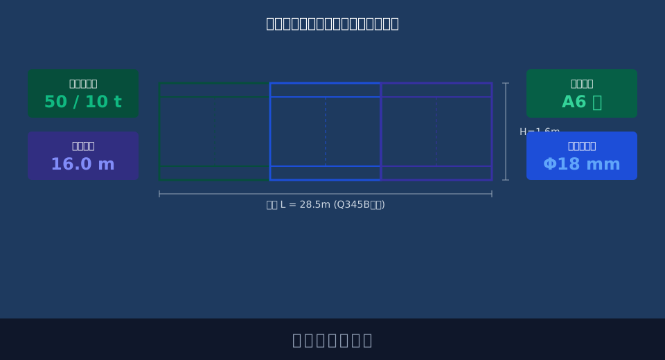
This article presents a comprehensive overview of the standardized workflow for replacing wire ropes on overhead cranes, covering five core dimensions: discard criteria assessment, reeving path planning, tension equalization testing, selection and lubrication management, and final acceptance trial runs. Our goal is to help maintenance teams avoid common operational pitfalls.
Overhead Crane Wire Rope Discard Criteria & Pre-Replacement Safety Preparation
Before initiating any replacement work, accurately determining whether the old wire rope has reached its discard criteria is the primary task. Blind replacements lead to unnecessary costs, while missed assessments create severe safety hazards. Maintenance personnel must conduct a thorough inspection of the entire wire rope length using vernier calipers and magnifying glasses.
According to industry standards, mandatory scrapping is required when the number of broken wires within one lay length reaches 30, or when surface steel wire wear exceeds 7% of the initial diameter. Additionally, if structural damage such as core protrusion, severe kinking, or local flattening is detected, immediate replacement is necessary even if the broken wire count does not meet the threshold. These specific data points serve as the core basis for on-site assessment.
Once the need for replacement is confirmed, strict safety preparation measures must be implemented. During the preliminary preparation phase, the crane's main power supply must be cut off, and a "Do Not Operate" warning sign must be hung on the control cabinet.
During the subsequent preparation phase, caution tape must be set up below the work area to prohibit unauthorized personnel from entering the lifting radius. Meanwhile, new wire rope coils, specialized slings, grease, and tension testing instruments must be prepared, ensuring all tools are verified and qualified.
"According to statistical reports from special equipment inspection institutes, approximately 45% of wire rope breakage incidents stem from failing to replace old ropes that have already met the broken-wire discard criteria. A standardized discard assessment process is the primary barrier to accident prevention."
⚠️ Note
When removing the old wire rope, you must first securely fix the lifting spreader using a hand chain hoist. This prevents the sudden drop of the spreader due to the loss of wire rope tension, which could cause equipment damage or personal injury.
Crane Drum & Pulley Block Reeving Methods & Path Planning Analysis
Reeving new wire ropes is a highly technical task; the reeving method directly impacts the service life of the wire rope and the operational smoothness of the crane. Common reeving methods include single-fall (straight) reeving and multi-fall (spiral) reeving. Single-fall reeving is easy to operate and results in more uniform wire rope wear. Multi-fall reeving effectively reduces torsional stress in the wire rope and is suitable for complex pulley blocks with large tonnage and high pulley ratios.
When planning the path, the deflection angle of the wire rope must be strictly controlled. Typically, the deflection angle when the wire rope enters or leaves the drum or pulley must not exceed 1.5 degrees. Excessive deflection causes severe friction between the wire rope and the sides of the pulley groove, accelerating groove wear and leading to wire rope jamming. When inspecting pulley block supports, if structural deformation caused by long-term excessive deflection is found, non-destructive testing should be performed on stress-concentrated areas, referring to the methods for weld crack detection.
To better understand the forces involved in reeving, let's look at a specific engineering case study. Consider an overhead crane with a lifting capacity of 50 t, where the lifting spreader weighs 5 t, the pulley ratio is 4, and the overall transmission efficiency of the pulley block is 0.95. We need to calculate the maximum static tension in a single wire rope.
The calculation process is as follows: Total lifting load P = (50 + 5) × 9.8 = 539 kN. Static tension in a single wire rope S = P / (pulley ratio × efficiency) = 539 / (4 × 0.95) ≈ 141.8 kN. Based on this tension value, combined with the safety factor (typically taken as 6), you can consult the selection manual to find the minimum breaking force required, thereby determining the appropriate wire rope diameter and construction.
"Reeving operations should follow the principle of 'from inside out, from bottom to top,' ensuring that the winding direction of the wire rope on the drum matches the helix direction of the drum's spiral groove to avoid cross-winding."
💡 Tip
After completing the reeving,Essential check the anti-derailment devices for all pulleys one by one. Ensure the gap between the rope guard plate and the pulley edge is less than 20% of the wire rope diameter to prevent the wire rope from jumping out of the groove during operation.
Multi-Rope Tension Adjustment Parameters & Equal Load Testing Methods
For cranes that use multiple wire ropes for simultaneous hoisting (such as certain ladle cranes or four-rope suspension systems), tension equilibrium among the ropes is crucial. Uneven tension causes ropes under higher load to undergo accelerated fatigue fracture, while those under lower load may slip on the drum. The core objective of tension adjustment is to keep the tension deviation of each rope within a reasonable range.
Industry standards typically require that the tension deviation among multiple wire ropes must not exceed 5% of the average value. Before adjustment, pre-tension should be applied to the wire ropes, generally set at around 10% of the rated working tension, to eliminate non-elastic elongation and installation gaps. During adjustment, the balance nuts on the lifting spreader's cross beam or the position of wedge sockets are adjusted to gradually equalize the load on each rope.
To scientifically evaluate the effectiveness of tension adjustment, professional testing tools are required. The table below details the application scenarios and precision parameters of different tension testing tools for reference by maintenance teams.
📊 Tension Adjustment Parameters and Testing Tool Performance Comparison
| TestingTool Type | measurement accuracy | Applicable Tension Range | Operational Convenience |
|---|---|---|---|
| Portable Digitaltension meter | ±0.5% FS | 0~500 kN | High,Direct Series Readout |
| HydraulicPillow BlockSensor | ±1.0% FS | 100~2000 kN | Medium,Requires Indicator Gauge |
| strain gauge-Type Force Ring | ±0.1% FS | 50~1000 kN | Low,Professional RequiredCalibrationinstallation |
After completing the wire rope selection for your tensioning tools, it is crucial to understand how lubrication and selection criteria vary across different operating conditions. These factors directly impact the long-term cost of equipment operation. The table below outlines the optimal selection and Lubrication Interval strategies for common scenarios.
📊 Wire Rope Selection and Lubrication Comparison by Operating Condition
| Applicationoperating condition | RecommendedWire rope construction | StandardRope diameterRange | Lubricationmaintenance cycle |
|---|---|---|---|
| StandardWorkshopMaterial Handling | 6×19S+FC Point Contact | 10mm~20mm | Per 180 Day |
| High TemperaturemetallurgicalCastingenvironment | 18×7 Multi-Layer Strand Anti-Rotation | 16mm~32mm | Per 90 Day |
| PortContainerFrequentLifting | 35W×7 Surface Contact | 20mm~40mm | Per 60 Day |
"Measured data indicates that in multi-rope hoisting systems, if the difference between maximum and minimum tension exceeds 8% of the average, the fatigue life of the most stressed rope shortens by approximately 30%. Load balancing is key to extending system service life."
⚠️ Safety Warning
During tension adjustment and testing, operators must stand in the safe zone on the side of the lifting spreader. Standing directly beneath the load or within the included angle where the wire rope might whip is strictly prohibited to prevent injury from accidental load detachment or rope breakage.
Anti-Rotation Wire Rope Selection Guide & Lubrication Maintenance Cycles
As cranes evolve toward large tonnage capacities and high lifting heights, traditional single-layer stranded wire ropes are prone to rotation and kinking when suspended freely, leading to uncontrolled suspended load sway. Modern anti-rotation wire ropes—featuring multi-strand or face-contact structures with opposing lay directions in inner and outer layers—effectively cancel out torque, becoming standard equipment for high-end cranes.
When selecting wire rope, prioritize nominal tensile strength and toughness. For equipment with a lifting height exceeding 30 meters (approx. 98 ft), multi-strand anti-rotation ropes with a diameter of at least 18mm are recommended. Lubrication management serves as a critical defense for maintaining performance. Under normal operating conditions, the lubrication interval is typically set to 90 days; however, in harsh environments characterized by high temperatures or heavy dust, this cycle should be reduced to 45 days or less.
Proper lubrication reduces internal friction between steel wires and prevents external corrosive agents from penetrating. For large tonnage applications, Kelude Heavy Industry’s technical team typically recommends specialized wire rope grease with high penetration capabilities, integrated with AI anti-sway algorithm control systems to enhance stability through both mechanical and electrical dimensions.
"When selecting grease, ensure its dropping point is at least 20°C above the ambient temperature. For metallurgical cranes, high-temperature grease containing extreme pressure additives like molybdenum disulfide is mandatory to prevent oil film rupture under heat."
💡 Pro Tip
Before applying new grease, thoroughly remove old lubricant and surface metal debris using a wire brush or compressed air gun. Applying fresh grease over contaminants is ineffective and accelerates abrasive wear on the wire rope.
Acceptance Standards & Trial Run Protocols After Bridge Crane Wire Rope Replacement
Following wire rope replacement and tension adjustment, rigorous acceptance checks and trial runs must be completed before official production use. During the acceptance phase, conduct a thorough examination of all fixing points (such as clamping plates and wedge sockets) to ensure they are secure and the rope arrangement is neat, free from entanglement or biting. Verify that all safety devices, including the Lifting Capacity Limiter and Height Limit Switch, have been recalibrated and respond sensitively.
Trial runs consist of three stages: no-load, rated load, and overload. The no-load test run observes the wire rope trajectory on the drum and pulleys to confirm there is no bouncing or abnormal friction noise. The rated load run verifies the reliability of the Hoisting and Lowering brakes, ensuring the braking distance meets design requirements. The Overload Test typically loads the crane to 1.25 times the Rated Lifting Capacity, holding the suspended load stationary for 10 minutes to check for permanent deformation or cracks in the wire rope and metal structure.
During the travel mechanism trial runs for Long Travel and Cross Travel, monitor the smoothness of the Travel Speed. For instance, if the Long Travel speed is set to 20 m/min, test the stability during acceleration and braking. Refer to the specifications for anti-collision safety distance to ensure buffers and limit switches trigger effectively within the designated range. Upon delivery, Kelude provides a comprehensive trial run manual to assist clients in completing this critical step according to operating regulations.
"The acceptance specification explicitly states that after the overload test, no loosening is permitted at any fixed parts of the wire rope. At least 3 safety wraps must remain on the drum to prevent the rope end from detaching due to excessive force."
⚠️ Safety Warning
During the 1.25x overload test, clear all unauthorized personnel from the work area and assign a dedicated safety officer for on-site supervision. No one is allowed to stand beneath the test weight to ensure absolute safety during the trial run.
Wire rope replacement and commissioning is a systematic engineering process. From discard criteria determination and threading planning to tension adjustment and final acceptance, every stage tests the professional competence of the maintenance team. As a manufacturer deeply rooted in the crane industry, Kelude Heavy Industry is committed to providing holistic solutions ranging from custom equipment manufacturing to full lifecycle maintenance, ensuring every crane operates safely and efficiently for industrial production.
FAQ
Q: How to determine the correct pulley ratio when replacing wire ropes?
A: The pulley ratio must strictly follow the original design drawings and nameplate parameters of the crane. The ratio dictates the distribution of Lifting Speed and wire rope tension. Altering the ratio without authorization can cause motor overload or substandard lifting speeds; calculations must be performed by a professional engineer before execution.
Q: What accuracy level is required for the tension meter during wire rope tension adjustment?
A: To ensure even stress distribution across multiple ropes, we recommend using a portable digital tension meter with an accuracy class of ±0.5% FS or better. For large tonnage cranes, select sensors with a matching Measuring Range that have undergone periodic calibration to keep tension Deviation within the permissible range of 5%.
Q: What is the cost difference between full replacement and partial replacement?
A: While full rope replacement involves higher upfront material cost, it eliminates the risk of uneven stress distribution, resulting in lower long-term maintenance costs. Partial replacement is only suitable for specific structure types and incurs high joint treatment fees. The exact cost difference depends on the rope length and capacity; all charges are subject to the actual contract.
Q: What precautions should be taken during the initial run-in period after putting new wire rope into operation?
A: New steel wire ropes typically undergo non-elastic elongation after approximately 50 hours of operation. At this stage, tension must be re-inspected and adjustment performed, along with applying Grease. During the run-in period, avoid Frequent starting under Full load. Only resume normal high-intensity operations once the wire rope has fully conformed to the pulley groove.
